Aller au contenu principal

BlackBerry 7510 Logic Board Replacement

Ce dont vous avez besoin

  1. BlackBerry 7510 Logic Board Replacement, Back Face of Phone: étape 1, image 1 de 1
    • Remove the battery cover and battery before continuing.

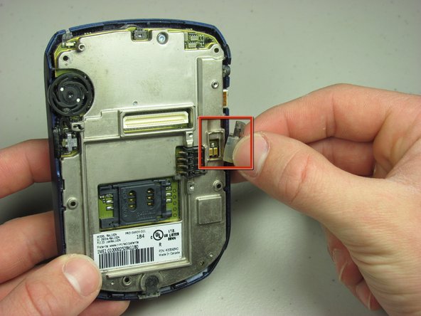
    • Remove the six T6 Torx screws on the back of the phone.

    • Make sure to keep the screws somewhere that they will not get lost.

  2. BlackBerry 7510 Logic Board Replacement: étape 2, image 1 de 1
    • Using your finger nail or a spudger, carefully pry up the back cover.

    • Begin in one spot and slowly circle around the device as you pry up all of the back cover.

  3. BlackBerry 7510 Logic Board Replacement: étape 3, image 1 de 1
    • Lift off the back cover.

  4. BlackBerry 7510 Logic Board Replacement: étape 4, image 1 de 1
    • Remove the two T6 screws.

  5. BlackBerry 7510 Logic Board Replacement: étape 5, image 1 de 2 BlackBerry 7510 Logic Board Replacement: étape 5, image 2 de 2
    • Remove the daughterboard.

    • Remove the exposed vibration motor.

  6. BlackBerry 7510 Logic Board Replacement, Logic Board: étape 6, image 1 de 1
    • Using the T6 Torx screwdriver, remove the top screw.

  7. BlackBerry 7510 Logic Board Replacement: étape 7, image 1 de 1
    • Using your spudger, carefully pry off back plate.

    • Use the same technique as with the plastic back cover. Circle around the back plate until all of it is pried up.

  8. BlackBerry 7510 Logic Board Replacement: étape 8, image 1 de 1
    • Remove the front cover and keypad.

  9. BlackBerry 7510 Logic Board Replacement: étape 9, image 1 de 1
    • Remove one T6 Torx screw in the front bottom right of the board.

  10. BlackBerry 7510 Logic Board Replacement: étape 10, image 1 de 2 BlackBerry 7510 Logic Board Replacement: étape 10, image 2 de 2
    • Carefully pry the screen from the board with your spudger.

    • After prying it up, remove the screen from the board.

  11. BlackBerry 7510 Logic Board Replacement: étape 11, image 1 de 2 BlackBerry 7510 Logic Board Replacement: étape 11, image 2 de 2
    • Unscrew center T6 Torx screw in the center of the logic board.

    • Remove the logic board from the phone.

    • Replace with new logic board.

Conclusion

To reassemble your device, follow these instructions in reverse order.

Neil Johnson

Membre depuis le 01/24/10

12 Réputation

6 tutoriels rédigés

Équipe

Cal Poly, Team 14-44, Regan Winter 2010 Membre de l'équipe Cal Poly, Team 14-44, Regan Winter 2010

CPSU-REGAN-W10S14G44

4 membres

8 tutoriels rédigés

0 commentaires

Ajouter un commentaire

Nombre de vues :

Dernières 24 heures : 3

7 derniers jours : 3

30 derniers jours : 3

Total : 1,849