Introduction
Use this guide to replace a damaged front bezel.
-
Use a coin to turn the battery locking screw 90 degrees clockwise.
-
Lift the battery out of the computer.
-
Remove the four Phillips screws from the memory door.
-
Slide the memory door away from the memory compartment.
Do you actually need to remove any of the screws on the underneath if you're just replacing a PRAM battery, or a hard drive? Aren't those only required if you're taking the whole logic board out?
-
Remove the following 8 screws:
-
Two 3 mm Phillips in the battery compartment, on either side of the battery contacts.
-
Two 9 mm Phillips on either side of the memory compartment.
-
Four 16 mm Phillips along the hinge.
-
-
Rotate the computer 90 degrees clockwise, so that the power receptacle faces you.
-
Remove the three 3 mm Phillips screws.
-
Turn the computer 90 degrees clockwise so that the hinge faces you.
-
Remove the bottom 5 mm Phillips screw on either side of the hinge (two total).
-
Rotate the computer 90 degrees clockwise, so that the ports face you.
-
Remove the three 3 mm Phillips screws.
-
Turn the computer over and open the display.
-
Remove the 4.2 mm 1/16" H 1.5 hex screws in either corner, next to the display (a T6 Torx driver will also do the job nicely).
-
Grasp the back corners of the upper case and pull up, disengaging hidden tabs on the sides. Do not pull the upper case off yet; you still need to free tabs in the front of the case.
I've opened the G4 four times. The official Apple way outlined above is vastly superior to the paper clip method. When you lower the screen side of the deck, a little bit of pressure toward you will easily release the clips. Definitely begin with the back (screen side) of the deck where you just remove the two T-6 screws.
-
Pry up the left side of the upper case slightly with your hand and wedge a spudger into the seam between the upper case and lower case.
-
Leave the tool in place applying pressure to the upper case for the next step.
This could really use a diagram to show exactly how the clip is structured. I didn't realize the clip was between the front of the case and the back support it attaches to, and it needs to be pried off that back support. (Evil Apple design - would it really hurt to have a screw underneath?). Overall these guides are fantastic! I just replaced a hard drive, and it worked great. And I LOVE the screw guide at the back - brilliant idea!
Apple official disassembly guide suggests instead to lift the upper case from the back up to 45 degrees. Then while lowering it back gently wiggle the upper case and it does disengage the latches. No tools required, no risk of bending the case.
This method worked perfectly for me. Lift at 45 degree angle and wiggle as slowly lower and it popped right off.
th3mamma -
-
Place enough pressure on the upper case to allow you to slide a tool just within the seam between upper case and lower case as shown in the picture. A dentist's hook, push pin, or similar tool will work.
-
Delicately slip the tip of your tool behind the silver metal latch and pull it forward while pulling up on the case. This may take some effort.
-
Alternatively, you can free the clasp with a small flathead screwdriver through the CD slot. The clasp is 1-3/16 in (3cm) from the left side of the slot. Use the screwdriver to lift out (or press back) the felt lining; then use the screwdriver to pull the clasp (shiny metal) forward to free it from the catch behind it (dull metal).
"Forward" (step 10) means toward the front. I was not able to release the latch this way. However, I did eventually release all three latches at once by very slightly lifting the rear of the cover and pressing the cover back toward the screen.
It is not necessary to remove the trackpad and keyboard cables (steps 12, 13, and 14) to replace the hard drive.
Quote from Pomo:
"Forward" (step 10) means toward the front. I was not able to release the latch this way. However, I did eveIt is not necessary to remove the trackpad and keyboard cables (steps 12, 13, and 14) to replace the hard drive.
I find it useful to use a big rubber band to hold the keyboard up--put it around the keyboard and display.
I've done several of these before, but today it was a bear to accomplish. I finally did it by inserting a dental pick through the optical slot and pulling forward to release the clip. In case it will help someone else, pictures of the clip are at Devil Clip.
-
Lift the back of the case up and work your fingers along the sides, freeing the case as you go. Once you have freed the sides, you may need to rock the case up and down to free the front of the upper case.
-
Rotate the upper case up and toward the screen, so that the upper case rests against it.
-
Remove the orange tape securing the trackpad ribbon to the logic board.
-
Disconnect the trackpad ribbon from the logic board.
-
1) With your fingernails, grasp the locking bar on either side and pull up a small amount (about 1/16" or 2 mm).
-
2) After disengaging the locking bar, slide the cable out of the connector.
Quote from ChrisT4:
Be very careful! The clasps holding the black strip are extremely fragile and can snap very easily.
In fact it is possible to get to your hard drive and replace it without having to detach this ribbon at all and I would advise that if all you are doing is replacing your hard drive then skip this step.
Yes, the note about skipping this step should be up there, front and center. I followed this step and broke the bit of plastic. Now it's re-fastened with a piece of electrical tape, but I am annoyed because it was totally unnecessary to do that. How do we edit the front page to at least say "OPTIONAL" for this step?
There should be a note on this to say this step is OPTIONAL. I followed instructions as written, broke the little plastic piece, and have taped it back together with electrical tape. But after replacing the hard drive, I see it was totally unnecessary to take this step. It's a high risk step, people should be warned.
the diagram is a bit confusing, and the text is a bit confusing for non english speakers. when it said pull up a small amount, i thought you have to try and lift it from the motherboard. all you have to do is move the black plastic bit towards the screen with your fingernails and the broad thing plastic keyboard cable comes off.
-
Loosen the keyboard ribbon clamp by pushing the thin black piece toward the screen, using the tips of your fingers.
-
Slide the grey keyboard ribbon out of the loosened connector.
-
Remove the upper case from the computer.
Watch this step carefully! The release mechanism pushes back slightly, parallel with the surface of the logic board. You may want to gently use a sparger rather than your thumbs if you have big fingers. This is a very delicate connector. Work one side slightly then the other. The good news is that it does not offer any resistance.
wcwirla -
-
Close the display and turn the hinge side of the computer to face you.
-
Remove the remaining Phillips screw on either side of the hinge (two screws total).
-
Open the computer with the display facing you.
-
Use a spudger to pry the bluetooth board from the gap between the battery housing and front of the lower case.
-
Disconnect the bluetooth antenna cable from the bluetooth board.
-
Deroute the bluetooth antenna cable along the left edge of the computer, removing tape as necessary.
-
Disconnect the large orange Airport ribbon from the logic board.
-
Pull the Airport ribbon cable up in order to access the black Airport antenna connector.
-
Disconnect the Airport antenna cable at the black connector, making sure you pull only on the black rubber portion of the connector.
It WAS the right guide, but my machine was missing an Airport cable connector, so I had to remove a half-dozen screws and a nut, loosening some black plastic that was screwed under the modem card, allowing access to remove the PCMCIA receptor (tricky getting it unhooked from the card ejector button), then removing the Airport card in order to unplug the cable.
-
Disconnect the inverter cable from the logic board.
-
Remove the two pieces of orange tape covering the display data cable and disconnect the cable from the logic board.
-
Remove the T8 Torx screw closer to the display on either side of the hinge (two screws total).
-
Remove the longer T8 Torx screw remaining on either hinge (two screws total).
-
Lift the display off.
-
Remove the two 11 mm X 1.5 mm hex screws near the lower left and right corners of the display.
-
Insert the flat end of a spudger between the front display bezel and the plastic rim attached to the rear bezel near the lower left corner of the display.
-
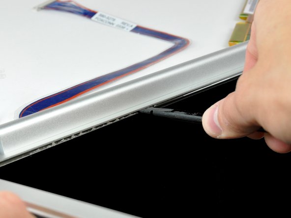
With your spudger still inserted under the front display bezel, run it around the lower left corner of the display.
-
Rotate the spudger away from yourself to pry the rear display bezel off the aluminum tabs on the front display bezel.
-
Work your way down the side of the display until the rear display bezel has been separated from the front display bezel.
-
Insert the flat end of a spudger between the rear display bezel and the clutch cover.
-
Twist the spudger to unclip the rear bezel from the clutch cover.
-
Repeat the previous steps to separate the right side of the rear display bezel from the display.
-
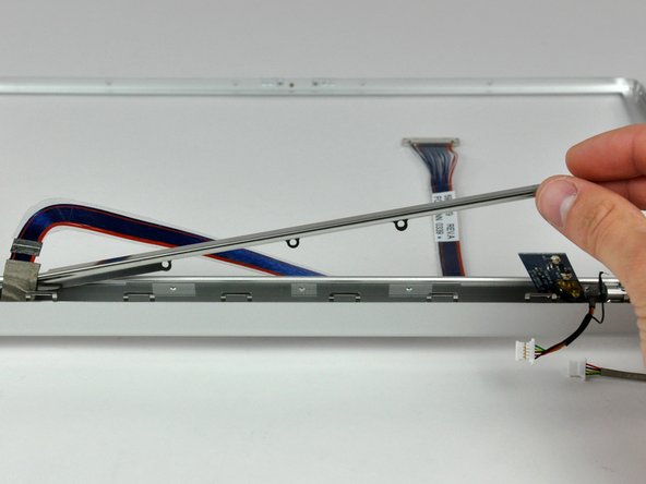
Use your spudger to pry the plastic retaining clips on the rear display bezel over the raised aluminum tabs on the front display bezel.
-
At this point, the clips on the left and right edges of the rear display bezel should be free from the raised aluminum tabs on the front display bezel. If they are not, use a spudger to pry them past the front display bezel.
-
Slightly lift the lower edge of the rear display bezel and push it toward the top edge of the display, releasing the clips along the top edge of the rear display bezel.
-
Rotate the rear display bezel toward yourself and lay it flat on the table.
-
Lift the antenna board out of the clutch cover.
-
Peel back the three edges of the antenna board cover and remove it from over the antenna board.
-
Use the flat end of a spudger to pry both antenna connectors up off the antenna board.
-
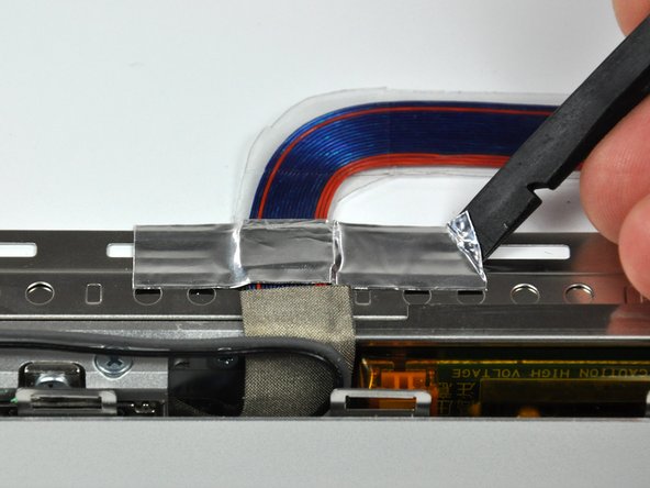
Use the flat end of a spudger to remove the piece of foil tape securing the display data cable to the LCD frame.
-
Pull the display data cable connector away from its socket to disconnect it from the LCD.
-
Remove the two black Phillips screws from either side of the display (four screws total).
-
Remove the four black Phillips screws along the top edge of the display.
-
Use a spudger to raise the end of the inverter out from the clutch cover.
-
Lift the inverter enough to access both cable connectors.
-
Disconnect the inverter cable by pulling its connector away from the socket on the inverter board.
-
Flip your display over so the front bezel is facing up.
-
Lift the front bezel off the LCD enough to insert the flat end of a spudger between the metal LCD frame and the front display bezel.
-
Run your spudger along the lower edge of the front display bezel to separate the adhesive from the LCD frame.
-
Pull the LCD toward the top edge of the front display bezel, minding any cables that may get caught.
-
Disconnect the inverter cable by pulling its connector away from the socket on the inverter board.
-
Remove the five Phillips screws securing the LCD retaining bracket to the front display bezel.
-
Lift the LCD retaining bracket off the front display bezel.
-
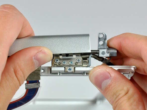
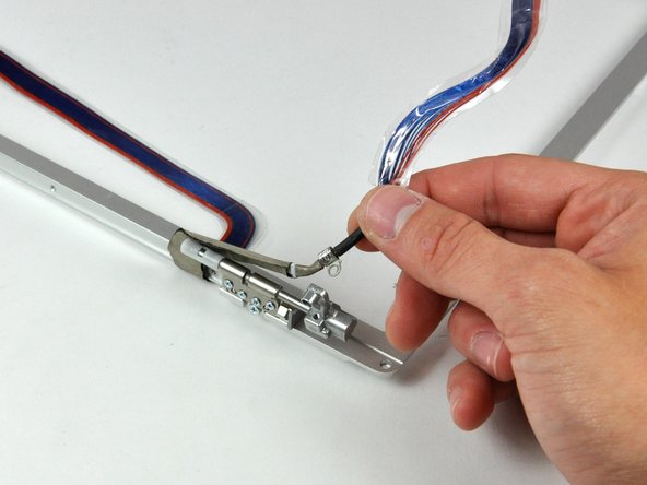
Use your thumbs to push the clutch cover away from the clutch hinges.
-
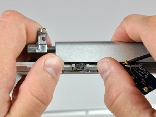
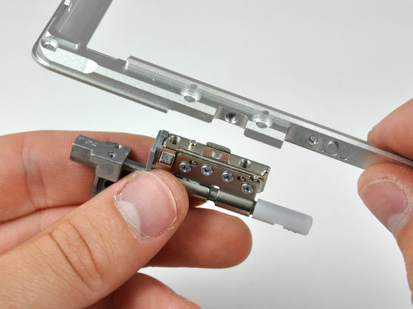
While pressing with your thumbs, rotate the clutch cover toward yourself about its long edge to pop it off the clutch hinge.
-
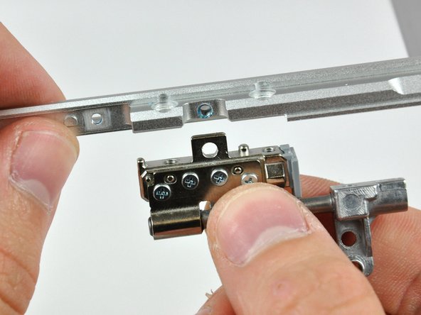
Repeat this process for the other side of the clutch cover. Once the clutch cover is completely free from the clutch hinges, lift it off the front display bezel.
-
De-route the inverter and display data cables from the clutch hinges and set them aside.
-
Remove the three Phillips screws securing the right clutch hinge to the front display bezel.
-
Remove the right clutch hinge and set it aside.
-
Remove the three Phillips screws securing the left clutch hinge to the front bezel.
-
Remove the left clutch hinge and set it aside.
-
Front bezel remains.
To reassemble your device, follow these instructions in reverse order.
Annulation : je n'ai pas terminé ce guide.
6 autre(s) ont terminé cette réparation.