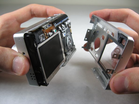
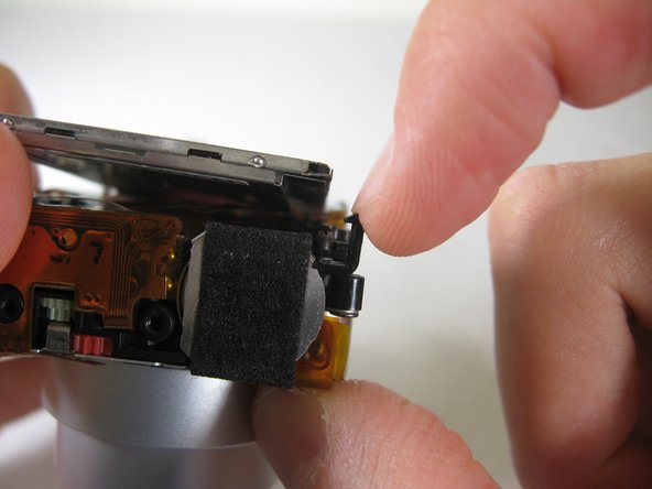
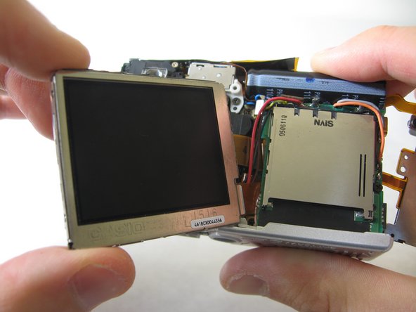
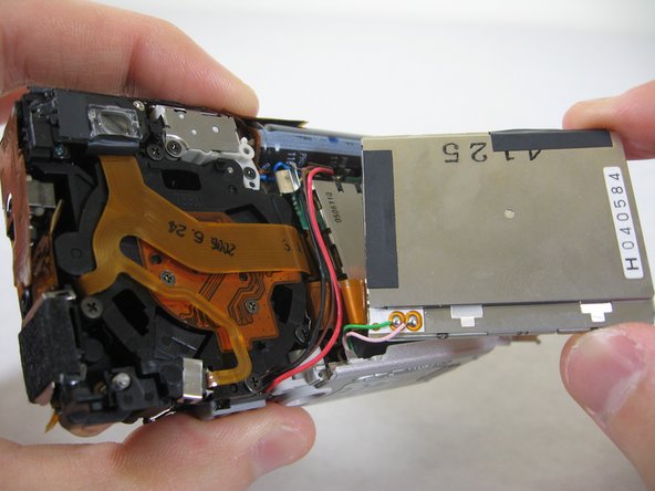
Aller au contenu principal

Accessing LCD Screen

Ce dont vous avez besoin

  1. Accessing LCD Screen, Front and Back Cover: étape 1, image 1 de 2 Accessing LCD Screen, Front and Back Cover: étape 1, image 2 de 2
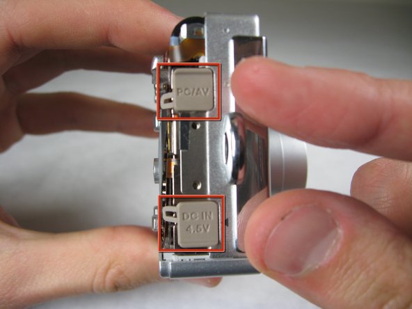
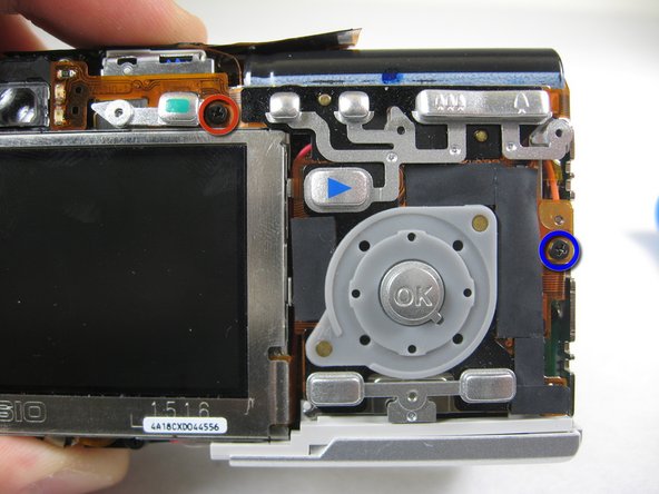
    • Remove the following screws:

    • Two silver 3.15mm Phillips #00 screws on the right side of the camera

    • Two silver 2.08mm Phillips #00 screws on the left side of the camera

  2. Accessing LCD Screen: étape 2, image 1 de 1
    • Remove the two indicated screws on the bottom of the camera:

    • The screw circled in red is a longer silver 3.15mm Phillips #00 screw

    • The screw circled in blue is a shorter silver 2.25mm Phillips #00 screw

  3. Accessing LCD Screen: étape 3, image 1 de 2 Accessing LCD Screen: étape 3, image 2 de 2
    • Carefully pull the back of casing away from the front.

  4. Accessing LCD Screen: étape 4, image 1 de 3 Accessing LCD Screen: étape 4, image 2 de 3 Accessing LCD Screen: étape 4, image 3 de 3
    • After removing the back cover, several things must be removed.

    • Silver donut-shaped button will fall off. Place separately. Remove the plug covers on the right side of camera, labeled “PC/AV” and “DC IN 4.5V”.

  5. Accessing LCD Screen: étape 5, image 1 de 2 Accessing LCD Screen: étape 5, image 2 de 2
    • To remove the front cover, gently hold the inside structure of the camera and slowly pull the front cover off.

  6. Accessing LCD Screen, LCD: étape 6, image 1 de 2 Accessing LCD Screen, LCD: étape 6, image 2 de 2
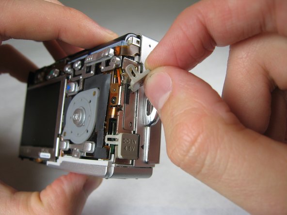
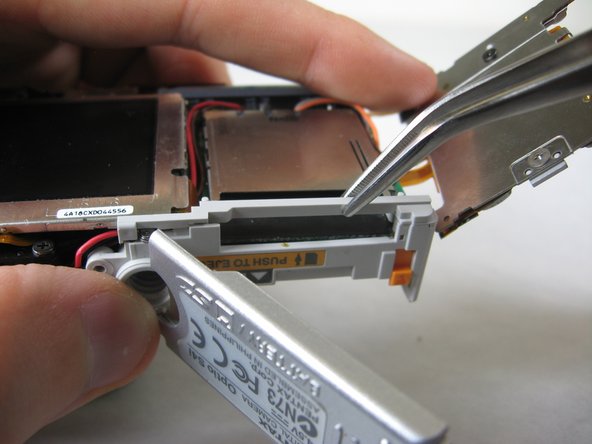
    • On the front of the camera, in battery case, remove screws indicated:

    • Two black 2.05mm Phillips #00 screws

  7. Accessing LCD Screen: étape 7, image 1 de 2 Accessing LCD Screen: étape 7, image 2 de 2
    • Flip the camera over to the backside and remove screws indicated:

    • The screw circled in red is a longer black 3.00mm Phillips #00 screw

    • The screw circled in red is a shorter black 2.00mm Phillips #00 screw

  8. Accessing LCD Screen: étape 8, image 1 de 1
    • Pull the cover plate off for the two power cord jacks.

  9. Accessing LCD Screen: étape 9, image 1 de 3 Accessing LCD Screen: étape 9, image 2 de 3 Accessing LCD Screen: étape 9, image 3 de 3
    • Cautiously and gently pull up the control board at the upper left corner, next to the viewfinder.

  10. Accessing LCD Screen: étape 10, image 1 de 1
    • Remove the orange tape on top of the SD cardholder.

  11. Accessing LCD Screen: étape 11, image 1 de 3 Accessing LCD Screen: étape 11, image 2 de 3 Accessing LCD Screen: étape 11, image 3 de 3
    • Open the battery cover and lift plastic piece off.

  12. Accessing LCD Screen: étape 12, image 1 de 1
    • Remove tape on left side of camera.

  13. Accessing LCD Screen: étape 13, image 1 de 1
    • Remove the indicated 2.40mm Phillips #00 screw to release top left LCD bracket.

  14. Accessing LCD Screen: étape 14, image 1 de 1
    • Remove top left LCD bracket.

    • This is a small piece, be careful not to lose it.

  15. Accessing LCD Screen: étape 15, image 1 de 2 Accessing LCD Screen: étape 15, image 2 de 2
    • Push down bottom left LCD bracket to release the LCD from grip.

  16. Accessing LCD Screen: étape 16, image 1 de 1
    • Gently lift up LCD screen.

  17. Accessing LCD Screen: étape 17, image 1 de 3 Accessing LCD Screen: étape 17, image 2 de 3 Accessing LCD Screen: étape 17, image 3 de 3
    • Slowly pull LCD screen to the left to remove it from the other grips.

    • BEWARE: The LCD screen is attached to the logic board by two wires at the bottom.

Conclusion

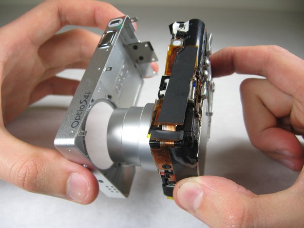
To reassemble your device, follow these instructions in reverse order.

Bassem Tossoun

Membre depuis le 01/21/11

201 Réputation

2 tutoriels rédigés

Équipe

Cal Poly, Team 4-29, Regan Winter 2011 Membre de l'équipe Cal Poly, Team 4-29, Regan Winter 2011

CPSU-REGAN-W11S4G29

3 membres

10 tutoriels rédigés

0 commentaires

Ajouter un commentaire

Nombre de vues :

Dernières 24 heures : 0

7 derniers jours : 1

30 derniers jours : 6

Total : 1,014