Cette version peut contenir des modifications incorrectes. Passez au dernier aperçu vérifié.
Ce dont vous avez besoin
-
Cette étape n’est pas traduite. Aidez à la traduire
-
Flip the laptop over so the model stickers face the ceiling.
-
-
Cette étape n’est pas traduite. Aidez à la traduire
-
Remove the two 3.5 mm Phillips #0 screws holding the cover in place.
-
Slide cover forward then carefully lift up.
-
-
Cette étape n’est pas traduite. Aidez à la traduire
-
Remove the two 5.5 mm Phillips #0 screws holding the battery in place.
-
-
-
Cette étape n’est pas traduite. Aidez à la traduire
-
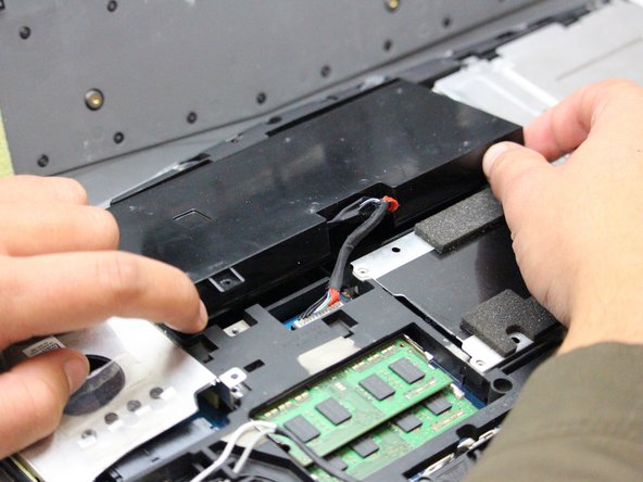
Carefully use the Plastic Opening Tool to unplug the battery.
-
Lift the battery up and out to remove.
-
-
Cette étape n’est pas traduite. Aidez à la traduire
-
Remove the following screws using a Phillips #0 screwdriver to free the motherboard from the rest of the internal components.
-
Twelve 5.5 mm Phillips #0 main frame screws.
-
Six 3.5 mm Phillips #0 fan screws.
-
Four 3.5 mm Phillips #0 internal compartment screws.
-
Eight 3.5 mm Phillips #0 Hard Drive screws.
-
Four 3.5 mm Phillips #0 CD Drive screws.
-
-
Cette étape n’est pas traduite. Aidez à la traduire
-
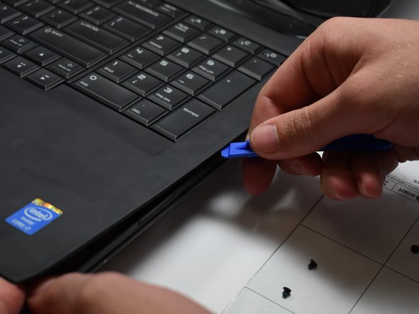
Flip the laptop over so that the Alienware logo is facing the ceiling and open the lid exposing the screen and keyboard.
-
Use a plastic opening tool to pry the keyboard from the base of the computer.
-
-
Cette étape n’est pas traduite. Aidez à la traduire
-
Remove five 3.5 mm Phillips #0 screws from the motherboard.
-
Unplug the consumer IR cables on the consumer IR board using a plastic opening tool.
-
Lift the motherboard at an angle and remove it from the computer base.
-


Équipe

Oregon Institute of Technology, Team S1-G2, Lancaster Fall 2018 Membre de l'équipe Oregon Institute of Technology, Team S1-G2, Lancaster Fall 2018
OIT-LANCASTER-F18S1G2
3 membres
5 tutoriels rédigés