Cette version peut contenir des modifications incorrectes. Passez au dernier aperçu vérifié.
Ce dont vous avez besoin
-
Cette étape n’est pas traduite. Aidez à la traduire
-
Insert the plastic opening tool behind the rear case to free the clips holding the case together.
-
Work your way around the device to free all the clips.
-
-
Cette étape n’est pas traduite. Aidez à la traduire
-
Once all clips have been released, remove the back case to reveal the inside of the device.
-
-
Cette étape n’est pas traduite. Aidez à la traduire
-
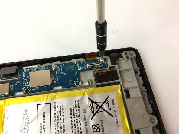
Remove the nine silver screws located around the motherboard with the T5 Torx screwdriver.
-
-
Cette étape n’est pas traduite. Aidez à la traduire
-
Remove the six black screws located around the battery and the speaker with the T5 Torx screwdriver.
-
Make your way around the battery and speaker to remove all of them.
-
-
-
Cette étape n’est pas traduite. Aidez à la traduire
-
Carefully unplug the three wire connections by placing a plastic spudger under the connections and lifting up.
-
Disconnect the battery and speaker connections by placing the round handle spudger under the wires and lifting up and out.
-
Disconnect the display connections from the motherboard by using the plastic spudger to lift the clamp holding the ribbon cable. Then, using the tweezers, grab the ribbon wire and pull away from the motherboard.
-
-
Cette étape n’est pas traduite. Aidez à la traduire
-
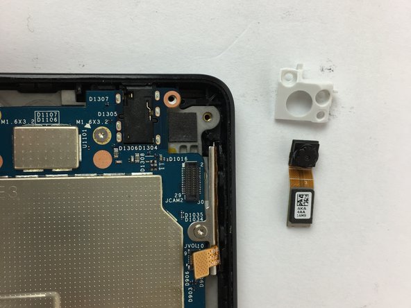
Remove the two screws holding the rear camera in place using the T5 Torx screwdriver.
-
Once freed from the screws, gently lift and remove the rear camera.
-
-
Cette étape n’est pas traduite. Aidez à la traduire
-
Now the motherboard is free to be removed.
-
Lift the motherboard up to remove it as shown in the picture.
-
-
Cette étape n’est pas traduite. Aidez à la traduire
-
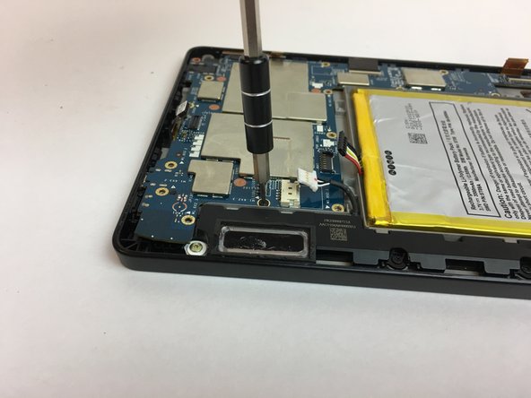
Following the bottom edge of the device, remove the (3) T5 hex silver screws with the T5 torx screwdriver.
-
-
Cette étape n’est pas traduite. Aidez à la traduire
-
The motherboard chassis can now be removed to reveal the display screen.
-
Remove the volume button components.
-
-
Cette étape n’est pas traduite. Aidez à la traduire
-
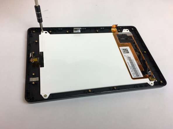
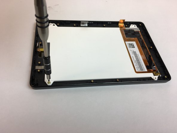
Remove the (4) T5 hex silver screws in the corners of the display screen using the T5 torx screwdriver.
-
-
Cette étape n’est pas traduite. Aidez à la traduire
-
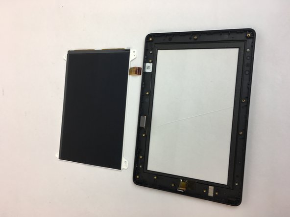
The LCD display screen may now be removed and replaced.
-


Annulation : je n'ai pas terminé ce tutoriel.
7 autres ont terminé cette réparation.
Équipe

USF Tampa, Team 4-4, Passmore Fall 2016 Membre de l'équipe USF Tampa, Team 4-4, Passmore Fall 2016
USFT-PASSMORE-F16S4G4
4 membres
10 tutoriels rédigés