Introduction
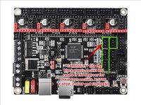
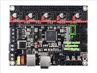
Replace the stock Trigorilla Pro motherboard with a BigTreeTech (BTT) SKR 1.4 (and Turbo) motherboard.
Parts of this guide were originally created by Kris Waclawski who has been an amazing resource for other Predator users.
Ce dont vous avez besoin
-
-
Remove the six M2 screws from the top panel. There are two on each side of the machine running along the outer edge.
-
-
-
Using the painters tape and a marker, label all the cables within the machine. This is useful when reinstalling the cables into the motherboard later, but it's also good to know what is what.
-
You should have the following labels: X, Y, Z, X stop, Y stop, Z stop, Hotend, T0 (Hotend thermistor), Fan 1, Fan 0, and Filament Sensor
-
-
-
Remove the seven screws that attach the motherboard to the case.
-
Unplug all the (now labeled) wires from the board.
-
Remove the motherboard and place in a safe place (ESD).
-
-
-
-
There's many options for stepper motor drivers. I've installed TMC2209s that were purchased with the board.
-
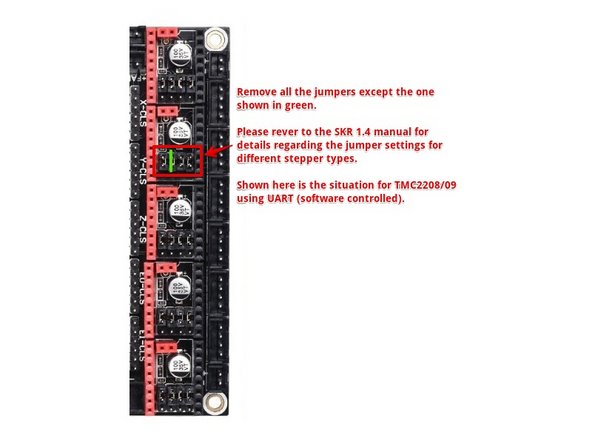
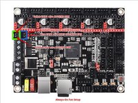
If you are installing the TMC2208/2209 drivers, then remove all the black jumpers located under the stepper driver sockets EXCEPT the one indicated in the diagram.
-
-
-
Insert the four wire stepper motor cables into the motherboard.
-
-
-
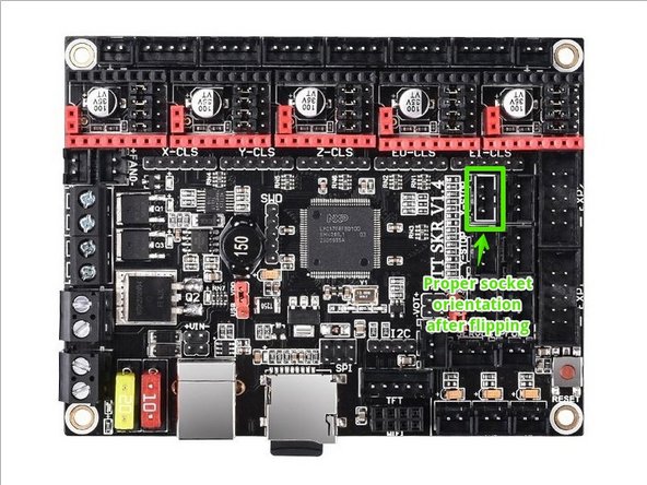
Take your needlenose pliers and slowly rock each socket back and forth, removing the socket from the board. The SKR has them installed the reverse that we need them, so we need to flip them 180 degrees from the stock installed direction.
-
Here is a gif of me flipping a socket on another board for reference: https://media.giphy.com/media/JonU7I9DJx...
-
-
-
Install the X-stop, Y-stop, Z-stop and Filament sensors onto the board in the marked spots.
-
-
-
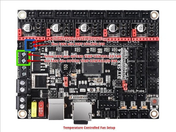
You have two options here. You can either let the software control the hotend fan, or leave it always on. There are benefits to both, and you can switch later on if you need to.
-
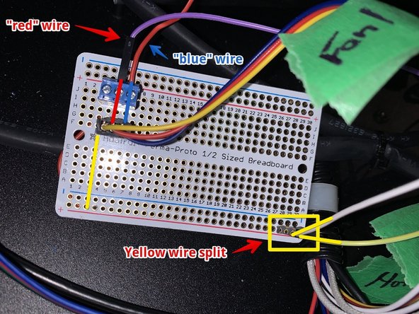
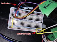
You will need to split the yellow wire coming from the FAN1 connector. I have done that using a small protoboard, but you can do that any number of ways.
-
To connect the part cooling fan you need to connect one line coming from the yellow FAN1 to the SKR FAN0 connector where marked. The blue FAN1 wire gets connected to the second SKR FAN0 pin. If possible, crimp them into a dupont/JST-SM connector to save yourself later.
-
If you are using the temperature-controlled hotend fan option (my recommendation using the stock hotends), then you connect one yellow FAN1 wire) to the HE1 connector where marked, and the red FAN1 wire to the other HE1 connector where marked.
-
If you are using the always-on hotend fan option (recommended if you're using all-metal heat break and upgraded hotends) then you connect one yellow FAN1 wire to the SKR FAN1 marked area, and connect the red FAN1 wire to the SKR FAN1 marked area.
-
-
-
Connect the white hotend wires from the predator to HE0.
-
Connect the hotbed wires coming from the MOFSET inside the machine to the BED screw terminals. White wire on top, red wire on the bottom as seen in the picture. Polarity matters.
-
Connect the 24V DC power from the power supply to the DCIN screw terminals. Be mindful of the polarity.
-
Connect the thermistors to TH0 (hot end thermistor) and TB (hotbed thermistor).
-
Connect the z-probe (marked LEVEL on the predator cable) to the PROBE connector. There's no polarity here, either way works as it's just a simple microswitch.
-


To reassemble your device, follow these instructions in reverse order.
To reassemble your device, follow these instructions in reverse order.
Annulation : je n'ai pas terminé ce tutoriel.
5 autres ont terminé cette réparation.

3 commentaires
How did you connected the Touchscreen? I don't see any step including connecting that flat cable for the screen.
I was mainly concentrating on the board wiring because it depends on what TFT you're using. For me, I was using the TFT35 V3 so I plug in EXP1 and EXP2 then the serial connection and it's good to go.