Il est possible que cette traduction ne reflète pas les dernières mises à jour du tutoriel source. Aidez à mettre à jour la traduction ou bien consultez le tutoriel source.
Introduction
L’entrée d’alimentation secteur est installée dans l’appareil et se trouve derrière quelques composants. Pour cette raison, de nombreux fils l'entourant ne font pas partie de ce composant spécifique. Assurez-vous de bien suivre les câbles et les composants pour vous assurer que les bonnes pièces ont été enlevées.
Ce dont vous avez besoin
-
-
Couchez l'écran avec l'écran vers le haut.
-
Placez les deux ventouses des deux côtés du haut de l’écran et assurez-vous de les verrouiller.
-
L'écran en verre à relier au reste de l'affichage par de petits aimants. Soulevez lentement et l'écran va se détacher.
-
-
-
Dévissez les 12 vis autour des bords latéraux et du haut de l’écran LCD avec le tournevis TR 10.
The screws marked in orange don't need to be removed, all they do is hold the magnets on the LCD.
Yes “orange screws” does not need to be removed.
You do not need a TR10 screwdriver as written in the text a T10 will suffice (more common and also correctly mentioned in the list of tools).
A TR10 screwdriver is compatible with the T10, but not the other way around
Any info on if an older 2011 imac screen could just be plugged into this to replace the current lcd?
-
-
-
Soulevez lentement l’écran LCD de son emplacement et inclinez-le vers le haut.
Add the note that it should be lifted from the bottom edge. It is also important not to twist the display by levering up from one corner.
Before lifting the monitor, you should be prepared to start collecting screws and have your TR 10 ready.
-
-
-
Pour le premier des quatre fils (le plus éloigné du fil retenu par une vis), saisissez le connecteur et tirez doucement.
Note: be sure to pull away but not hard. Wiggle and pull slowly. These are delicate especially due to age.
Overall this is a moderate repair. Follow step by step and you are good.
Also, use tape and/or labels to mark which cables go where per the MLB and other parts. Resulting in easier reassembly.
-
-
-
Pour le connecteur suivant, juste à côté du fil précédent, un morceau de ruban adhésif est attaché à une barre de métal.
-
Retournez la barre de métal en utilisant le ruban comme poignée.
-
Ensuite, saisissez le connecteur et retirez-le lentement de la prise de la carte mère.
What is this connector for?
I imagine this connector is going to be for display data (i.e. LCD data).
I pretty much mangled this cable trying to put it back into the slot. Is this something I can order a replacement for?
Thunderbolt Display 27" LVDS Cable
As other’s have said, this cable is super delicate.
When you replace it, make sure that the small metal handle it firmly reattached to the other side of the port. I thought I’d got it right first time, but had no video signal (thunderbolt detected display, and power was fed to the Macbook Pro).
I had to reinsert this one again, and one in, firmly press the connector home, then latch the handle over the other side. I also gave it a test pull to ensure it was secure. Then all was well!
Can anyone provide a photo of this connector so as to give a better understanding of its mechanics? see this cringe worthy effort at guidance; https://youtu.be/A96CUSm_Xhs?t=1050
-
-
-
-
Pour le connecteur situé de l’autre côté de la carte mère, saisissez-le par le dessous et retirez-le délicatement de la carte.
This cable was also taped for me, so remove the tape first
-
-
-
L'écran LCD est maintenant complètement déconnecté du boîtier et peut être réparé / remplacé!
-
-
-
Vous devriez maintenant voir l'entrée d'alimentation secteur au centre de l'appareil (bien que retenu par quelques autres composants).
-
Suivez les fils qui sortent du bas de l’adaptateur secteur vers la gauche.
-
Prenez la pince à épiler et retirez le morceau de ruban adhésif qui maintient les fils au boîtier.
-
Un seul connecteur doit être débranché (même s’il y en a deux juste à côté!).
-
Saisissez le connecteur par le bas et tirez-le délicatement de la prise correspondante.
Yes - pictures and last bullet point are misleading and confusing respectively. I suggest fixit should remove the second picture and replace it with a picture of the connector that should be removed and amend the last bullet point o read something like 'depress the clip that holds the left connector in place and carefully etc ...'
Avoid the verb 'grab'
Yes, grab has no finesse at all. Grabbing and ripping are what makes the whole process a potential nightmare :)
-
-
-
Le composant de haut-parleur environnant (la boîte noire) autour de la prise d'alimentation doit être retiré.
-
Utilisez le tournevis TR 10 pour retirer les quatre vis.
-
Déconnectez l'enceinte de derrière la carte mère en tirant doucement sur l'extrémité en plastique du câble.
-
Retirez le haut-parleur.
If you are only replacing the Thunderbolt and MagSafe cable, steps 11-13 do not need to be performed ie speaker and EMI filter do not need to be removed, only the screw holding the grounding cable on the EMI filter (top left of round disk).
I concurr with M Baynes.
-
-
-
Maintenant que l'enceinte centrale est à l'écart, l'adaptateur secteur est facilement accessible.
-
À l'aide d'une pincette, retirez le ruban argenté situé en haut de l'adaptateur.
I can’t help but notice that this assembly that is called an EMI (Electromagnetic Interference) Filter is in the exact position that my monitor has been displaying a band of disrupted color bands once it heats up. I am changing the Thunderbolt cable assembly in hopes that is fixes the problem. If it doesn’t then I will make changing the Filter my next quest. It is also noteworthy that the Filter is grounded to the case by the metal tape which must be peeled back for this procedure. Hmmm.
-
-
-
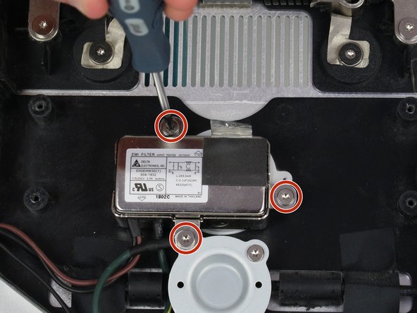
L'adaptateur d'alimentation est connecté par trois vis. Utilisez le tournevis T10 pour les supprimer.
-
Le fil vert et jaune retenu par la vis différente est dissimulé derrière un autre composant. Pour le sortir, pincez-le derrière le fil noir pour pouvoir débrancher l'adaptateur secteur du boîtier.
Nothing about the power cable itself here. That has to be unplugged first, or when you get to this point, you’ll have to carefully unplug the main power cable from the back of the AC adapter you just removed in Step 13, and feed it through the hole in the back of the case.
-


Pour remonter votre appareil, suivez ces instructions dans l’ordre inverse.
Pour remonter votre appareil, suivez ces instructions dans l’ordre inverse.
Annulation : je n'ai pas terminé ce tutoriel.
11 autres ont terminé cette réparation.
Merci à ces traducteurs :
33%
[deleted] nous aide à réparer le monde ! Vous voulez contribuer ?
Commencez à traduire ›
Équipe

Cal Poly, Team 5-11, Maness Spring 2015 Membre de l'équipe Cal Poly, Team 5-11, Maness Spring 2015
CPSU-MANESS-S15S5G11
4 membres
19 tutoriels rédigés
7 commentaires
Power adapter? That's the AC EMI filter, right? My power supply looks like this:
http://www.dvwarehouse.com/661-6048-661-...
The EMI filter will never fail... well, maybe a direct lightning strike.
That is definitely just a filter. The power supply is the big PCB connected to it. One could say this is an EMI filter along with an IEC input connector...this guide is only useful if you want to replace the connector rather than the actual power supply.
Not sure if the EMI filter will NEVER fail as someone said above. Mine was buzzing and I replaced it and this fixed one of my displays that was buzzing. There are also other causes, including capacitors on the Power Supply board, worn out fan etc.
So are we saying that this is wrong? anyone? I really need to replace my power supply.
I replace the all in one lightning and charge cable but it has ended up that the lightning cable only works. I thought I connected everything up fine but which connector would stop the charge cable working?
Am I imagining things, or was there once a separate power supply guide? I bought the part, and now I can't seem to find that particular guide.. I had the buzzing sound, and now my display won't even turn on-- do I have to replace both, would you think?
Display is going out afther 1 hour of working. I have replace the power supply. But afther installation I still had this problem.
Then I ordered a new Logicboard. and a new cable. Afther installation I still had the same problem !!!. :(
Is it possible that the filter is broken, or the display of the A1407.??
Instead of $14 foam block, I used a full roll of paper towel and two pillows. While it worked, if I ever did this again, I would buy the block of foam. Since you’re removing a power cable, you need to be able thread it through and I think the foam block would make that easier.
Josh Miller - Réponse
You can also use a single handle, double cup floor lifting suction cup. Just place it in the centre of the screen near the camera and lift slowly.
Steve A - Réponse
I just used a toilet plunger to remove the screen and it worked like a charm!
Philip Jacob - Réponse
That’s what I call resourceful—made my day. I hope your repair was successful.
Tobias Isakeit -
Great idea, thanks a lot!
Yvan Sandoz -
The glass lifted off the magnets quite easily after just using my fingernails. No suction cups or toilet accessories needed.
Adrian Gropper - Réponse
I had the same problem and after removal of the fan and a bit of work with the vacuum, the fan is quiet. Thanks to ifixit for the great instructions that made this easy.
John Perser - Réponse
To keep the screen up, other soft objects might work, but it's important that the hole in the back isn't covered because you will need to thread the new Thunderbolt/MagSafe cable through it and it would be a hassle to do it after everything's been set up.
Thomas - Réponse
Anybody got any links to glass screen replacement supplier for the A1407 Thunderbolt Display? Im finding it impossible to find a replacement without it being crazy money.
Michael McMillan - Réponse
Instead of a wedge, I used 4 rolls of toiletpaper, one under each corner.
jnbruin - Réponse