Cette version peut contenir des modifications incorrectes. Passez au dernier aperçu vérifié.
Ce dont vous avez besoin
-
Cette étape n’est pas traduite. Aidez à la traduire
-
Remove the two round rubber feet at the hinge-edge of the laptop.
-
-
Cette étape n’est pas traduite. Aidez à la traduire
-
Remove the eleven 4 mm Phillips #00 screws from the back panel.
-
-
Cette étape n’est pas traduite. Aidez à la traduire
-
Using a plastic opening tool pry the back panel off of the laptop.
-
-
Cette étape n’est pas traduite. Aidez à la traduire
-
Pull the speaker cable out of its four retaining clips with either your fingers, or a plastic opening tool.
-
-
Cette étape n’est pas traduite. Aidez à la traduire
-
Remove all seven 2 mm Phillips #00 screws from the battery.
-
-
Cette étape n’est pas traduite. Aidez à la traduire
-
Pull the speaker connector toward the edge of the laptop to disconnect it from its socket.
-
-
-
Cette étape n’est pas traduite. Aidez à la traduire
-
Lift the battery connector straight up off its socket to disconnect it from the motherboard.
-
-
Cette étape n’est pas traduite. Aidez à la traduire
-
Lift the battery and speakers up and pull out to remove.
-
-
Cette étape n’est pas traduite. Aidez à la traduire
-
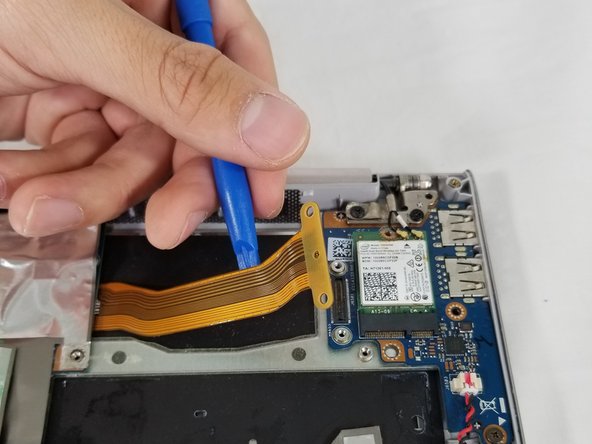
Disconnect the display cable from the motherboard with a plastic opening tool.
-
-
Cette étape n’est pas traduite. Aidez à la traduire
-
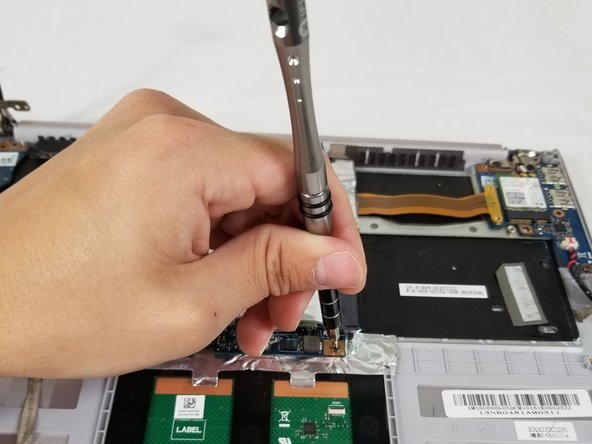
Remove the three 6mm Phillips #00 screws from the hinge.
-
Remove the 2mm Phillips #00 screw from the plastic housing securing the fan into place.
-
-
Cette étape n’est pas traduite. Aidez à la traduire
-
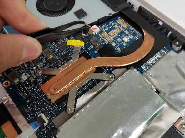
Lift the screen assembly hinge up and off of the motherboard fan.
-
-
Cette étape n’est pas traduite. Aidez à la traduire
-
Using tweezers, disconnect the cable connector from the motherboard fan.
-
-
Cette étape n’est pas traduite. Aidez à la traduire
-
Lift the fan up and off of the white pegs that secure it into place.
-
-
Cette étape n’est pas traduite. Aidez à la traduire
-
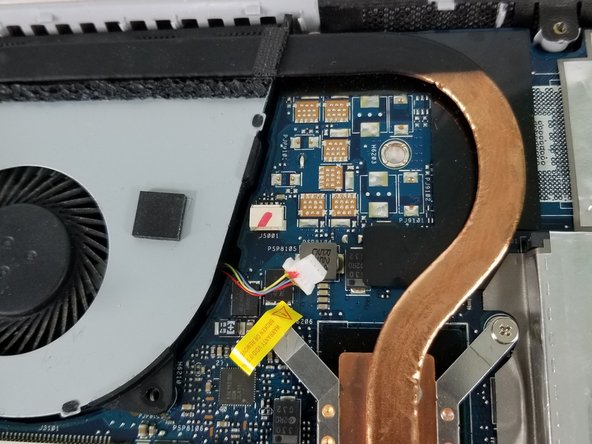
Disconnect all wires connecting the motherboard to the rest of the device.
-
For the two connectors marked in orange, lift the black clip up to release the wire.
-
For the wire marked in yellow, lift it straight up.
-


Annulation : je n'ai pas terminé ce tutoriel.
4 autres ont terminé cette réparation.
Équipe

USF Tampa, Team S3-G5, Nance Spring 2018 Membre de l'équipe USF Tampa, Team S3-G5, Nance Spring 2018
USFT-NANCE-S18S3G5
3 membres
9 tutoriels rédigés
Un commentaire
The bottom of the pictured device may feature Phillips #00 screws, but I also have this laptop and the screws around the edge of the bottom panel are Torx T5s on my device.