Ce dont vous avez besoin
-
-
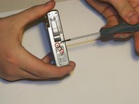
Turn the camera over so that the battery compartment is visible. The compartment should read "Card/Batt. Open".
-
Open the compartment.
-
Lightly push the compartment lid down and outward. The arrow next to "Card/Batt. Open" indicates the direction you should be pushing.
-
-
-
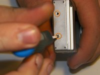
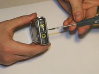
There are six 3mm exterior screws that will need to be removed in order to remove the exterior frame.
-
Two screws near the tripod mount on the underside of the camera.
-
Two screws on the camera left hand side (the face with nothing but screws on it).
-
Two screws on the camera right hand side, by the wrist strap attachment.
-
Remove the screws using the screwdriver.
-
-
-
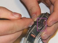
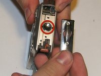
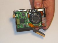
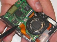
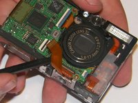
Carefully pull apart the two parts of the exterior frame.
-
Use the spudger to pry apart the two frame components.
-
Once disconnected, the two parts of the frame can be easily separated by using your fingers.
-
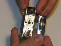
The rear frame should be removed first.
-
There should be an O-ring on the front face of the camera. Ensure to keep the O-ring with the front part of the frame.
-
-
-
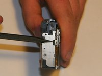
The power and shutter buttons are located on the top of the camera and are removed as a single unit.
-
Use the spudger to lift the power/shutter buttons from the camera.
-
-
-
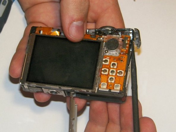
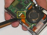
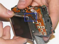
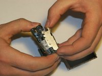
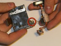
Disconnect the cable that connects the screen to the front motherboard.
-
Using a spudger, unsnap the jawbone connector that holds the cable in
-
Gently pull the cable out using the spudger.
-
-
-
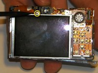
At the back of the camera, there are four 2.5mm screws that will need to be removed in order for the screen to pull off.
-
One at the top of the camera that is connected to a bracket that secures the screen.
-
Two on the back of the camera,near the speaker.
-
One hidden behind the bracket.
-
-
-
Outil utilisé dans cette étape :Tweezers$4.99
-
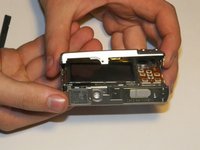
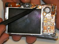
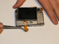
Gently lift the screen and pull it apart from the camera, taking care to unslot the screen brackets from the tabs on the bottom and left side of the camera.
-
Do not pull too hard on the screen as there is still another delicate cable running from the screen to the rear board of the camera.
-
Gently pull the wide ribbon (shown in an earlier step) cable from the front of the camera to the back using tweezers.
-
-
-
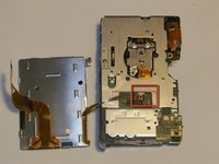
The screen is now connected only by a small cable that runs to the rear board of the camera. Using tweezers, slowly pull the cable out of the connector.
-
For best results, grip the cable as close to the connector as possible.
-
The screen should now be separate from the camera body. Be careful not to harm the connectors on the lens so it will reconnect successfully.
-
-
Outil utilisé dans cette étape :Tweezers$4.99
-
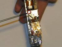
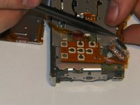
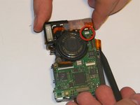
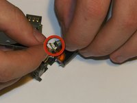
First it is necessary to remove the ribbon cable connecting the control board to the [green] rear accessory board on the camera.
-
This is done by unsnapping the jawbone connector and gently pulling the cable out with tweezers or the spudger.
-
-
-
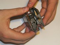
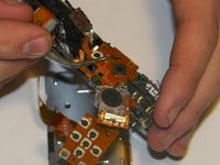
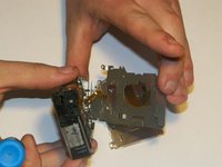
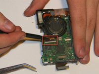
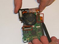
Using the spudger, gently push up the board from the pins underneath it.
-
Follow the board up and around the camera, gently unseating the board and cables.
-
The speaker will still be connected to the board via two small power wires. Use the tweezers to pull and unplug the power connector from the main rear accessory board.
-
-
-
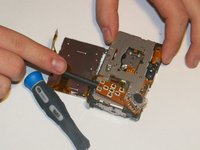
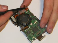
There are six 3mm screws located on the interior frame.
-
Remove the screws with the screwdriver.
-
-
-
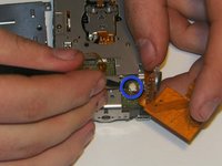
There are two 3.25mm screws that hold the tripod mount in the camera.
-
The first screw is located on the back of the camera above the tripod mount.
-
The second screw is located on the lens side of the camera above the tripod mount.
-
Remove the second screw using the Phillips 00 Screwdriver.
-
-
-
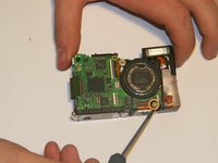
There are three screws that will need to be removed if they have not done so already.
-
-
Outil utilisé dans cette étape :Tweezers$4.99
-
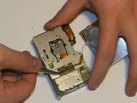
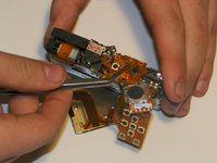
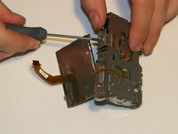
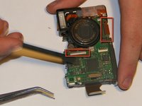
There is one main ribbon cable that needs to be disconnected from the motherboard using the pudger and tweezers.
-
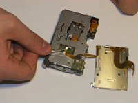
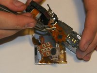
It is best to remove the flash assembly at the same time as the lens and motor assembly.
-


To reassemble your device, follow these instructions in reverse order.
To reassemble your device, follow these instructions in reverse order.
Équipe

Clemson, Team 13-5, Benson Spring 2013 Membre de l'équipe Clemson, Team 13-5, Benson Spring 2013
CLEM-BENSON-S13S13G5
3 membres
11 tutoriels rédigés