Aller au contenu principal

Canon ZR70MC LCD Component Replacement

Ce dont vous avez besoin

  1. Canon ZR70MC LCD Component Replacement, Front Panel: étape 1, image 1 de 2 Canon ZR70MC LCD Component Replacement, Front Panel: étape 1, image 2 de 2
    • Unscrew the 3.35mm screw.

  2. Canon ZR70MC LCD Component Replacement: étape 2, image 1 de 1
    • Turn the ZR70MC so that you can see the bottom of the camcorder.

    • Unscrew the 3.35 mm located in the top left portion of the camera.

  3. Canon ZR70MC LCD Component Replacement: étape 3, image 1 de 3 Canon ZR70MC LCD Component Replacement: étape 3, image 2 de 3 Canon ZR70MC LCD Component Replacement: étape 3, image 3 de 3
    • Turn the camera on the side and remove the cover for the audio inputs. There is a 2.65 mm screw located behind the cover.

    • Remove the 2.65 mm screw.

  4. Canon ZR70MC LCD Component Replacement: étape 4, image 1 de 3 Canon ZR70MC LCD Component Replacement: étape 4, image 2 de 3 Canon ZR70MC LCD Component Replacement: étape 4, image 3 de 3
    • Remove the cover located on the front of the camcorder and remove the cover by pulling on the bottom groove.

    • Locate and remove the two 3.35 mm screws.

  5. Canon ZR70MC LCD Component Replacement: étape 5, image 1 de 2 Canon ZR70MC LCD Component Replacement: étape 5, image 2 de 2
    • Turn the camcorder so that the bottom is facing up and open the tape cassette compartment.

    • There is one 3.35 mm screw located under the tape cassette panel on the front left side of the camcorder. Remove the screw.

  6. Canon ZR70MC LCD Component Replacement: étape 6, image 1 de 3 Canon ZR70MC LCD Component Replacement: étape 6, image 2 de 3 Canon ZR70MC LCD Component Replacement: étape 6, image 3 de 3
    • Now that all of the screws are removed, remove the front panel by gently pulling on the front panel.

    • The speaker will be connected to the main body by a wire. Be careful not to damage this wire.

  7. Canon ZR70MC LCD Component Replacement: étape 7, image 1 de 3 Canon ZR70MC LCD Component Replacement: étape 7, image 2 de 3 Canon ZR70MC LCD Component Replacement: étape 7, image 3 de 3
    Outil utilisé dans cette étape :
    Tweezers
    $4.99
    J'achète
    • Use tweezers to gently pull the speaker wire from the main body of the camcorder.

    • Pull the front panel completely away from the main body of the camcorder.

  8. Canon ZR70MC LCD Component Replacement, LCD screen: étape 8, image 1 de 3 Canon ZR70MC LCD Component Replacement, LCD screen: étape 8, image 2 de 3 Canon ZR70MC LCD Component Replacement, LCD screen: étape 8, image 3 de 3
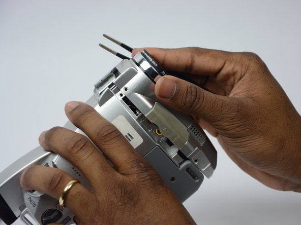
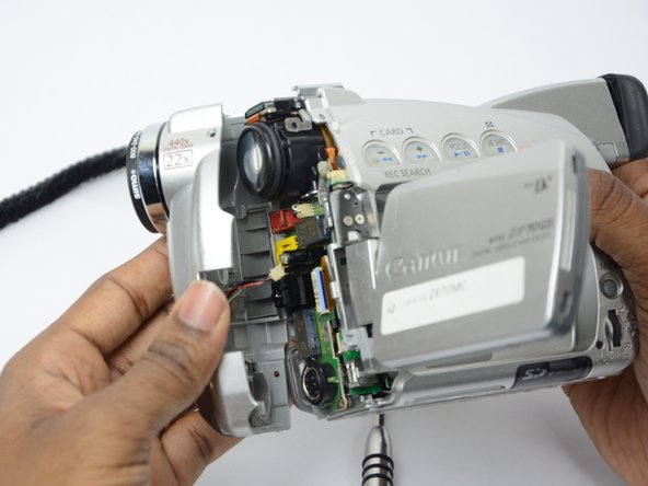
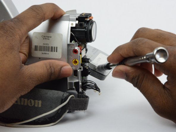
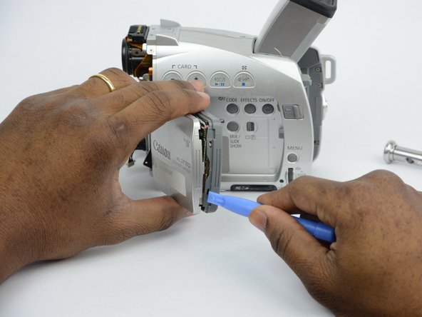
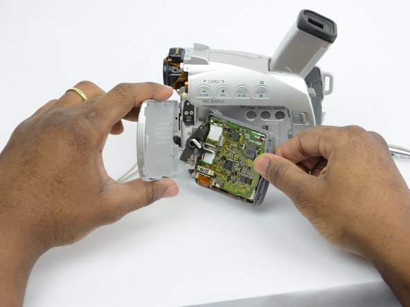
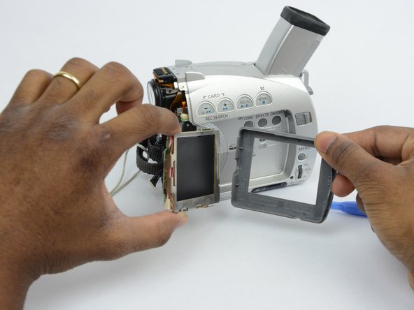
    • Open the LCD screen.

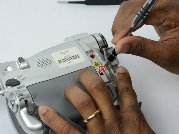
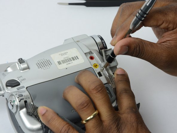
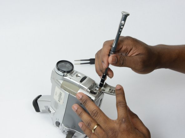
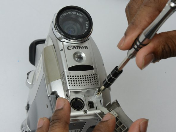
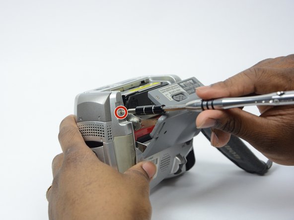
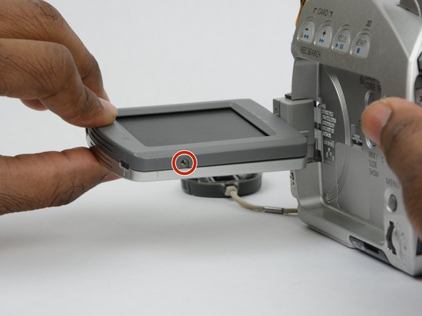
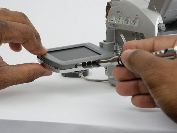
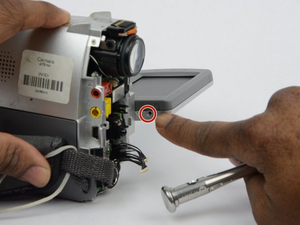
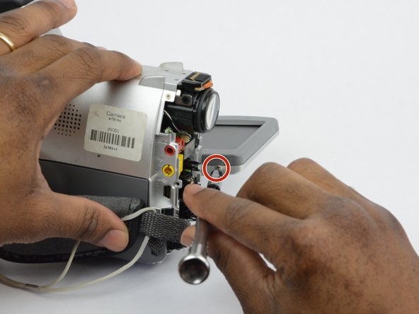
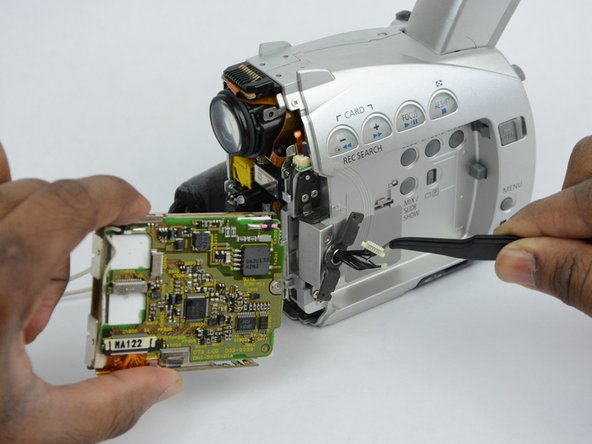
    • Locate and remove the 2.7 mm screw on the bottom of the LCD monitor.

  9. Canon ZR70MC LCD Component Replacement: étape 9, image 1 de 3 Canon ZR70MC LCD Component Replacement: étape 9, image 2 de 3 Canon ZR70MC LCD Component Replacement: étape 9, image 3 de 3
    • Turn the LCD monitor so that the screen is facing down.

    • There is a 2.7 mm screw on the LCD monitor where the monitor is connected to the main body of the camcorder. Remove the 2.7 mm screw.

  10. Canon ZR70MC LCD Component Replacement: étape 10, image 1 de 2 Canon ZR70MC LCD Component Replacement: étape 10, image 2 de 2
    • Turn the LCD monitor so that the screen is facing up.

    • There is a 2.7 mm screw located where the LCD monitor is connected to the main body of the camcorder. Remove the 2.7 mm screw.

  11. Canon ZR70MC LCD Component Replacement: étape 11, image 1 de 3 Canon ZR70MC LCD Component Replacement: étape 11, image 2 de 3 Canon ZR70MC LCD Component Replacement: étape 11, image 3 de 3
    • Now that all the screws are removed, use the plastic opening tool to gently pry the LCD monitor case open.

  12. Canon ZR70MC LCD Component Replacement: étape 12, image 1 de 3 Canon ZR70MC LCD Component Replacement: étape 12, image 2 de 3 Canon ZR70MC LCD Component Replacement: étape 12, image 3 de 3
    Outil utilisé dans cette étape :
    Tweezers
    $4.99
    J'achète
    • Use tweezers to remove the wire connections that hold the LCD screen in place.

    • Remove the entire LCD screen.

Conclusion

To reassemble your device, follow these instructions in reverse order.

Une autre personne a terminé cette réparation.

khalid clarke

Membre depuis le 09/26/17

824 Réputation

7 tutoriels rédigés

Équipe

USF Tampa, Team S13-G2, Boczar Fall 2017 Membre de l'équipe USF Tampa, Team S13-G2, Boczar Fall 2017

USFT-BOCZAR-F17S13G2

3 membres

14 tutoriels rédigés

0 commentaires

Ajouter un commentaire

Nombre de vues :

Dernières 24 heures : 1

7 derniers jours : 5

30 derniers jours : 9

Total : 175