Cette version peut contenir des modifications incorrectes. Passez au dernier aperçu vérifié.
Ce dont vous avez besoin
-
Cette étape n’est pas traduite. Aidez à la traduire
-
Remove the five 3/8" screws from the base of the kettle using a Phillips #1 screwdriver.
-
-
Cette étape n’est pas traduite. Aidez à la traduire
-
Using your hands, pry the base off the kettle.
-
Open the kettle like a clamshell; the ON/OFF switch will be the hinge point.
-
-
Cette étape n’est pas traduite. Aidez à la traduire
-
Using your hands, remove the kettle base by sliding it over the switch.
-
-
Cette étape n’est pas traduite. Aidez à la traduire
-
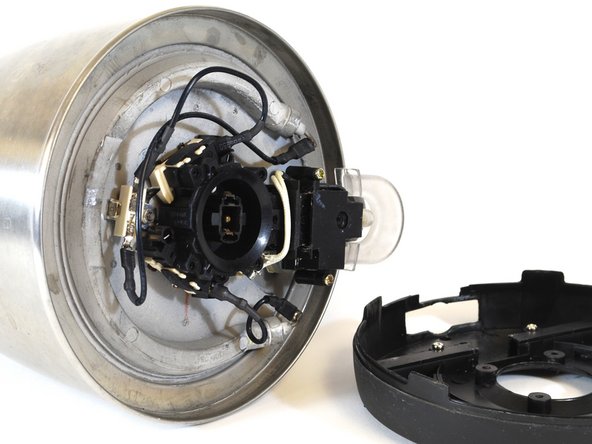
A: The power supply.
-
B: The two boil-dry protection switches, one on either side of the central black ring.
-
C: The power coupling. This fits into the baseplate when you place the kettle on it.
-
D: The thermostat. This is a little metal ring, half hidden by the switch cover.
-
E: The manual ON/OFF switch.
-
F: The indicator light.
-
G: The steam chamber. This heats the thermostat, which turns off the kettle automatically.
-
-
-
Cette étape n’est pas traduite. Aidez à la traduire
-
Remove the connectors (spaded lugs) from the circuit components as shown in the second image.
-
You should be able to remove each connector easily by hand. Pinch the lug between your fingers and pull in the direction of the attached wire.
-
If necessary, use needle-nose pliers to grasp the lug shank firmly. Gently pull the lug in the direction of the attached wire.
-
Gently bend the disconnected wires back and out of the work area.
-
-
Cette étape n’est pas traduite. Aidez à la traduire
-
Using a 7/32" nut driver, remove the hex nut that secures the power supply to the base of the kettle.
-
Using a pair of tweezers, remove the split-ring lock washer located under the nut. (It may be hard to see in low light.)
-
-
Cette étape n’est pas traduite. Aidez à la traduire
-
Using your hands, grasp the wire that is still connected to the power supply. Carefully lift the power supply off the threaded stud to which it was coupled.
-
Five (5) screws.
-
The kettle base.
-
One (1) 7/32'' hex nut.
-
One (1) 7/32" split-ring lock washer.
-
One (1) power supply unit.
-
-
Cette étape n’est pas traduite. Aidez à la traduire
-
FIRST IMAGE: Remove the power supply. Align the kettle as shown, with the handle to your right. Use the 7/32" nut driver to remove the 7/32" nut from the stud that is located clockwise from where the power supply was attached.
-
Use tweezers to remove the split-ring lock washer located under the nut.
-
SECOND IMAGE: Roll the kettle over so the handle is now on your left. Use the 7/32" nut driver to remove the 7/32" nut from the final stud, which is now located counter-clockwise from where the power supply was attached.
-
Use tweezers to remove the split-ring lock washer located under the nut.
-
-
Cette étape n’est pas traduite. Aidez à la traduire
-
Grasp the control switch with one hand and the kettle with the other.
-
Gently rock the control switch while simultaneously pulling it away from the bottom of the kettle.
-
Pull the switch completely off the kettle.
-
-
Cette étape n’est pas traduite. Aidez à la traduire
-
The yellow arrows show how the studs align with the switch brackets.
-
The blue arrow shows how the steam tube aligns with the steam chamber on the switch thermostat.
-


Annulation : je n'ai pas terminé ce tutoriel.
8 autres ont terminé cette réparation.
Équipe

New Mexico State, Team 1-1, Sheppard Spring 2014 Membre de l'équipe New Mexico State, Team 1-1, Sheppard Spring 2014
NMSU-SHEPPARD-S14S1G1
4 membres
3 tutoriels rédigés
Un commentaire
OK, now I can look from the bottom. But why the switch does not keep down when I press it down I can not see or repair.
Robert