Cette version peut contenir des modifications incorrectes. Passez au dernier aperçu vérifié.
Ce dont vous avez besoin
-
Cette étape n’est pas traduite. Aidez à la traduire
-
Turn the power switch, the leftmost knob, counterclockwise to off.
-
-
Cette étape n’est pas traduite. Aidez à la traduire
-
Turn the device around and firmly pull the power cable plug to remove it from the radio.
-
-
Cette étape n’est pas traduite. Aidez à la traduire
-
Unscrew the securing cap counterclockwise from the antenna connector.
-
-
Cette étape n’est pas traduite. Aidez à la traduire
-
Gently pull the antenna cable to remove it from the back of the radio.
-
-
Cette étape n’est pas traduite. Aidez à la traduire
-
Unscrew the cap counterclockwise on the microphone plug to disconnect the cable.
-
-
-
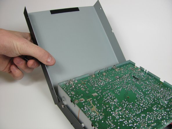
Cette étape n’est pas traduite. Aidez à la traduire
-
Unscrew the top four 6.0mm Phillips head screws counterclockwise on the left and right side of the device using a #1 Phillips head screwdriver.
-
-
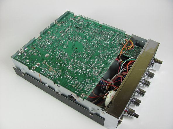
Cette étape n’est pas traduite. Aidez à la traduire
-
Unscrew the four 6.0mm Phillips head screws counterclockwise on the left and right side of the device that connect the remaining cover, using a #1 Phillips head screwdriver.
-
-
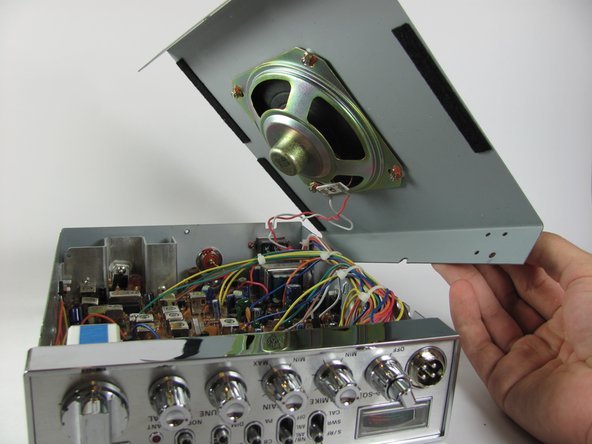
Cette étape n’est pas traduite. Aidez à la traduire
-
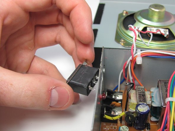
Unscrew the two 6mm Phillips screws counterclockwise, using a #1 Phillips head screwdriver.
-


Annulation : je n'ai pas terminé ce tutoriel.
2 autres ont terminé cette réparation.
Équipe

Cal Poly, Team 11-37, Amido Fall 2013 Membre de l'équipe Cal Poly, Team 11-37, Amido Fall 2013
CPSU-AMIDO-F13S11G37
4 membres
9 tutoriels rédigés
4 commentaires
Difficulty Difficult? this is the easiest thing you can do to one of these radios.
thank you, i’m hoping this will help but i doubt it, i had too big of a fuse in mine and it took a spike hit and lost all power a few years back but i’d really like to get this fixed.
Any idea what the board pin hole number is that the black cord from the negative goes into? I’ve got a 2018 29 LX
Not sure. There is a partial schematic available at www.cbtricks.com