Cette version peut contenir des modifications incorrectes. Passez au dernier aperçu vérifié.
Ce dont vous avez besoin
-
Cette étape n’est pas traduite. Aidez à la traduire
-
Identify the lock mechanisms holding the battery in place.
-
Slide each button outward with your fingers to disengage the battery.
-
Pull the battery off with your hand to separate it from the laptop.
-
-
Cette étape n’est pas traduite. Aidez à la traduire
-
Find the two small indentations of the sides of the panel covering the power button.
-
Pry up both sides of the panel by sticking the plastic opener tool in each indentation and prying up.
-
-
Cette étape n’est pas traduite. Aidez à la traduire
-
Now that the panel is loose simply pull the panel off with your hand.
-
-
Cette étape n’est pas traduite. Aidez à la traduire
-
Locate the two 5 mm Phillips #1 screws holding down the keyboard that were underneath the panel.
-
Remove these screws with a Phillips #1 screwdriver.
-
With the screws removed pull the keyboard up with your hand.
-
-
Cette étape n’est pas traduite. Aidez à la traduire
-
Locate the connector that links the keyboard to the laptop.
-
Gently pull the connector toward the screen of the laptop with your figers to disconnect it.
-
-
-
Cette étape n’est pas traduite. Aidez à la traduire
-
Locate the two Phillips #1 screws holding the Wireless Local Area Network (WLAN) panel in place.
-
Remove these two screws with a Phillips #1 screwdriver.
-
Remove the WLAN panel by pulling it up with your hand.
-
-
Cette étape n’est pas traduite. Aidez à la traduire
-
Disconnect the black and white wires attached to the WLAN card by pulling up on the connectors with your fingers.
-
Remove the remaining wires from their protective sleeve by hand.
-
-
Cette étape n’est pas traduite. Aidez à la traduire
-
Pull the wires that you disconnected in the previous step through the hole in the top of the laptop.
-
-
Cette étape n’est pas traduite. Aidez à la traduire
-
Detach the Phillips #1 grounding screw with a Phillips #1 screwdriver.
-
Disconnect the display cable by pulling up on the rectangular tab with your fingers.
-
-
Cette étape n’est pas traduite. Aidez à la traduire
-
Disconnect the camera/microphone cable by prying it upward with the plastic opener tool.
-
Separate the camera/microphone cable from the case by pulling it up with your fingers.
-
-
Cette étape n’est pas traduite. Aidez à la traduire
-
Remove the two 10 mm Phillips #1 screws from the bottom of the laptop that attach the lid assembly to the laptop with a Phillips #1 screwdriver.
-
Remove the two 10 mm Phillips #1 screws from the back of the laptop that also attach the lid assembly to the laptop with a Phillips #1 screwdriver.
-
-
Cette étape n’est pas traduite. Aidez à la traduire
-
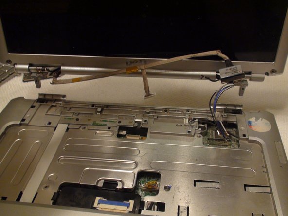
Remove the lid by pulling it up from the base of the laptop with both hands.
-
-
Cette étape n’est pas traduite. Aidez à la traduire
-
Locate the six 5 mm Phillips #1 screws connecting the display bezel to the back cover.
-
Remove the six screws with a Phillips #1 screwdriver.
-
-
Cette étape n’est pas traduite. Aidez à la traduire
-
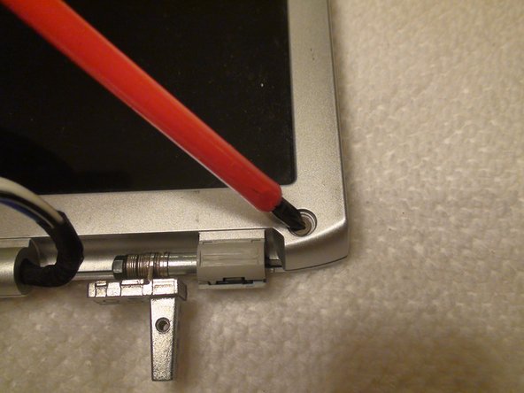
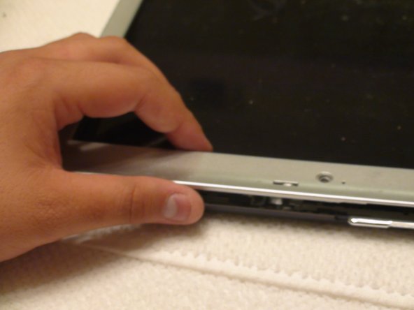
Use a plastic opener tool to begin separating the bezel from the display assembly.
-
Move around the edges of the bezel with your hand or a plastic opener tool in order to loosen it from the display assembly.
-
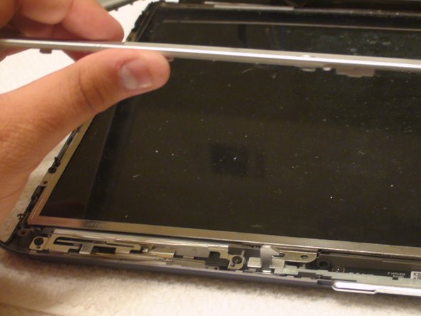
Once the bezel is loose, remove it from the display assembly by hand.
-
-
Cette étape n’est pas traduite. Aidez à la traduire
-
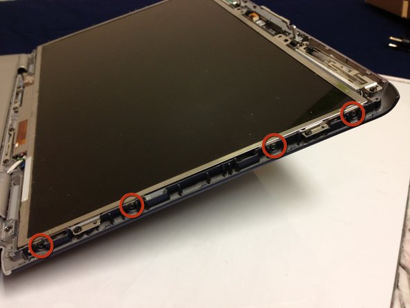
Locate the eight 4 mm Phillips #1 screws (four on each side of the LCD) that secure the display to the assembly.
-
Remove the eight screws with a Phillips #1 screwdriver.
-
-
Cette étape n’est pas traduite. Aidez à la traduire
-
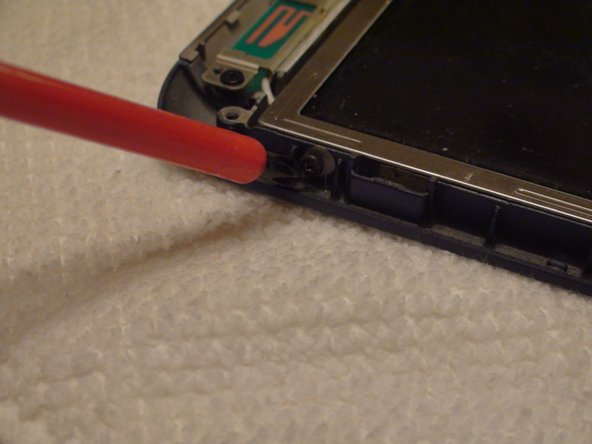
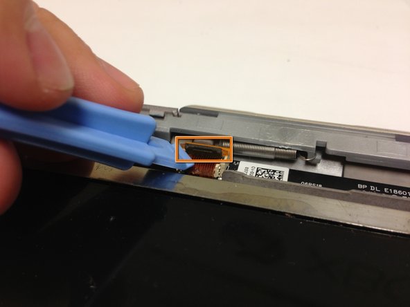
Locate where the LCD display cable connects to the housing.
-
Lift the black tab with your finger or a plastic opener tool.
-
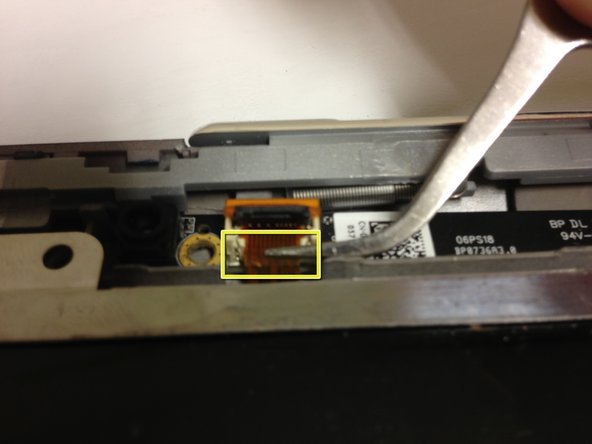
Gently pull on the cable with tweezers to disconnect it.
-
-
Cette étape n’est pas traduite. Aidez à la traduire
-
Carefully lift and remove the LCD display with both hands.
-


Annulation : je n'ai pas terminé ce tutoriel.
2 autres ont terminé cette réparation.
Équipe

Cal Poly, Team 15-47, Forte Fall 2012 Membre de l'équipe Cal Poly, Team 15-47, Forte Fall 2012
CPSU-FORTE-F12S15G47
5 membres
9 tutoriels rédigés