Cette version peut contenir des modifications incorrectes. Passez au dernier aperçu vérifié.
Ce dont vous avez besoin
-
Cette étape n’est pas traduite. Aidez à la traduire
-
Start by turning the computer around, and remove this #0 Phillips Screw.
-
-
Cette étape n’est pas traduite. Aidez à la traduire
-
Now lift these two clips, and slowly pivot the case up.
-
You can now seperate the top of the computer from the rest of the machine.
-
-
Cette étape n’est pas traduite. Aidez à la traduire
-
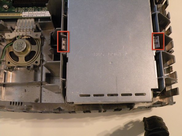
The "SuperDrive" is mounted similarly to the hard drive, and positioned right next to it.
-
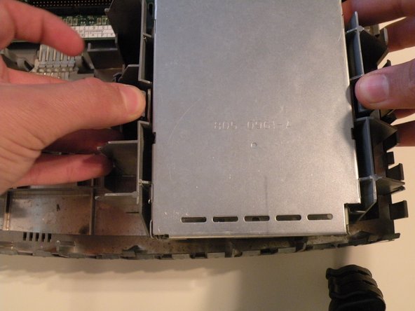
Push these two tabs out, and lift the drive up.
-
-
-
Cette étape n’est pas traduite. Aidez à la traduire
-
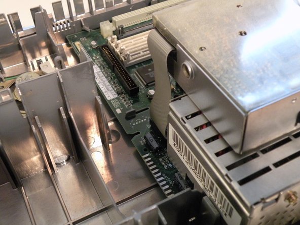
Flip the drive so it is on top of the power supply, and remove the "Red-Ribbon" cable.
-
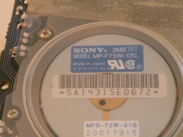
This drive was manufactured by Sony in 1990.
-
-
Cette étape n’est pas traduite. Aidez à la traduire
-
The fan recieves power from two contacts on the logic board and has no connector.
-
-
Cette étape n’est pas traduite. Aidez à la traduire
-
In all of the years that I have worked on this machine, I have found no good way to remove the fan.
-
The best way to start, is to push in here on the side of the fan.
-
Being careful not to exert too much force, try to push in, and wiggle the fan outward as such. (2nd Photo)
-
You can now lift the fan all the way out, and remove it.
-
The Fan Power Contacts on the Logic Board:
-
-
Cette étape n’est pas traduite. Aidez à la traduire
-
To remove the power supply, squeeze these two tabs and lift the front up.
-
On the back of the power supply, there is a tab that also must be pressed to remove the power supply fully. You can then lift it out all the way. A firm tug may be necessary to seperate the power connector.
-
-
Cette étape n’est pas traduite. Aidez à la traduire
-
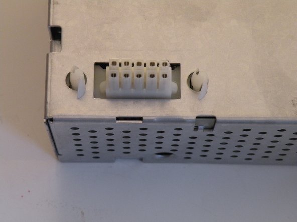
Information on the power supply:
-
It was made by Sony in 1990, and uses a 10-Pin power connector.
-


Annulation : je n'ai pas terminé ce tutoriel.
2 autres ont terminé cette réparation.

Équipe
