Cette version peut contenir des modifications incorrectes. Passez au dernier aperçu vérifié.
Ce dont vous avez besoin
-
Cette étape n’est pas traduite. Aidez à la traduire
-
Turn the camera upside down.
-
Place your thumb on the switch, and slide it towards the center of the camera.
-
-
Cette étape n’est pas traduite. Aidez à la traduire
-
Once you have the battery compartment open, slide the orange tab away from the battery until it ejects.
-
-
Cette étape n’est pas traduite. Aidez à la traduire
-
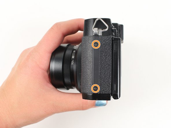
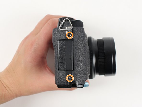
Begin by removing the outside screws using a Phillips #000 Screwdriver:
-
Remove the three 3.6 mm silver screws located on the bottom of the camera.
-
Remove all four of the 4.7 mm screws from the sides of the camera.
-
-
Cette étape n’est pas traduite. Aidez à la traduire
-
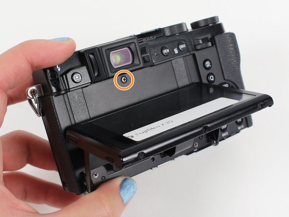
Remove all screws below using a Phillips #000 Screwdriver:
-
Lift up the screen and remove the two 4.5 mm screws located in the bottom corners.
-
Remove the 4.0 mm screw that is located behind the screen and directly under the eye piece.
-
-
-
Cette étape n’est pas traduite. Aidez à la traduire
-
Carefully lift up the bottom piece of the camera to remove it.
-
-
Cette étape n’est pas traduite. Aidez à la traduire
-
Gently pull off the back of the camera from the left side so that it is partially open.
-
Use a spudger to lift up the tab holding the orange strip and slide the strip out to disconnect it
-
-
Cette étape n’est pas traduite. Aidez à la traduire
-
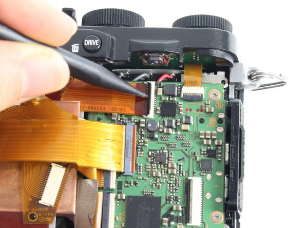
For all five indicated orange strips:
-
Use a spudger to lift up the tab holding the orange strip and slide the strip out to disconnect it.
-
-
Cette étape n’est pas traduite. Aidez à la traduire
-
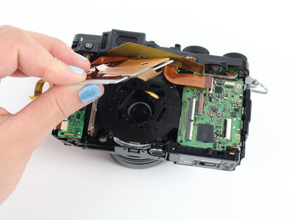
For the last orange strip located behind the top strip:
-
Use a spudger to lift up the tab holding the orange strip and slide the strip out to disconnect it.
-
-
Cette étape n’est pas traduite. Aidez à la traduire
-
For the two orange strips attached to the capacitor circuitboard:
-
Use a spudger to lift up the tab holding the orange strip and slide the strip out to disconnect it.
-
-
Cette étape n’est pas traduite. Aidez à la traduire
-
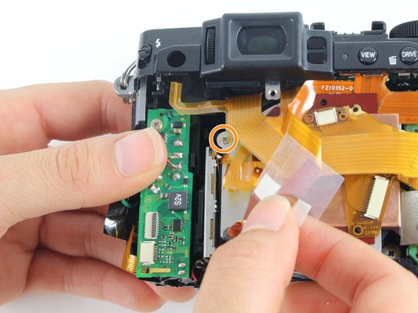
Remove all screws listed below using a Phillips #000 screwdriver:
-
Remove the two 3.4 mm screws at the bottom of the silver plate.
-
Hold back the clear strip to reveal a 2.8 mm screw on the left of the silver plate and remove it.
-
Peel back the copper plate.
-
-
Cette étape n’est pas traduite. Aidez à la traduire
-
Remove the three 2.6 mm screws located in the top two corners and the bottom right corner of the motherboard using a Phillips #000 screwdriver.
-
-
Cette étape n’est pas traduite. Aidez à la traduire
-
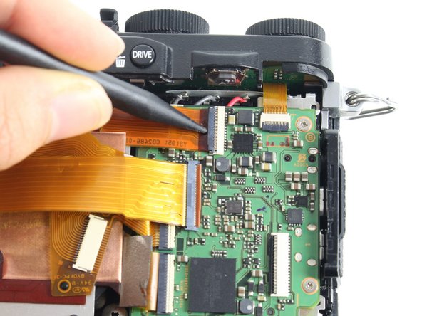
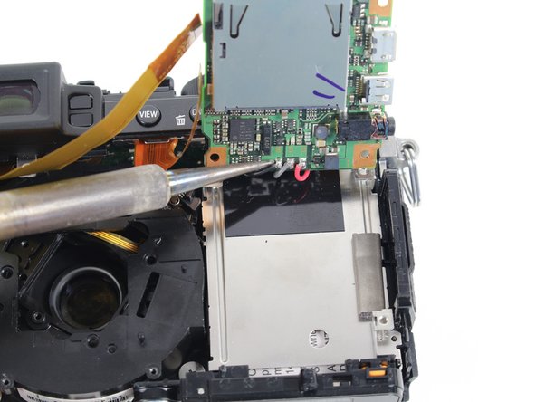
Tilt up the motherboard to locate the black, grey, and red wires.
-
Desolder these wires in order to completely remove the motherboard.
-


Annulation : je n'ai pas terminé ce tutoriel.
2 autres ont terminé cette réparation.
Équipe

Cal Poly, Team 70-3, Forte Winter 2016 Membre de l'équipe Cal Poly, Team 70-3, Forte Winter 2016
CPSU-FORTE-W16S70G3
5 membres
4 tutoriels rédigés
2 commentaires
On step 11 becareful not to detach flex surface from aluminium plate. You could end up braking CCD contacts as I did.