Ce dont vous avez besoin
-
Cette étape n’est pas traduite. Aidez à la traduire
-
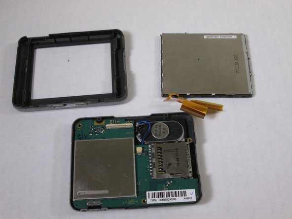
Top left: back casing
-
Top right: front casing
-
Middle left: speaker. Part ($29) and service at portatronics.com
-
Middle right: motherboard
-
Bottom left: battery. Part ($5.20) at amazon.com
-
Bottom right: LCD screen. Assembly kit ($49) at portatronics.com
-
-
Cette étape n’est pas traduite. Aidez à la traduire
-
The Serial Number Strip is at the base of the device. Remove it to two expose two T5 Torx screws.
-
Using the T5 Torx screwdriver, remove the two T5 Torx screws.
-
-
Cette étape n’est pas traduite. Aidez à la traduire
-
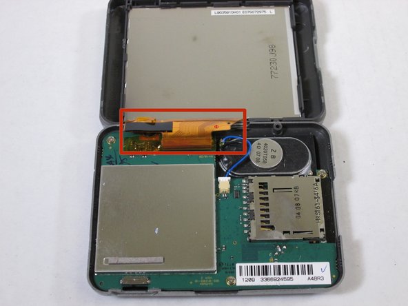
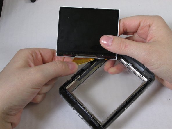
Use care. Do no break apart the strip of orange tape that connects the LCD screen and motherboard (red box in third picture.)
-
Using the plastic opening tool, only at the bottom of the device, separate the back panel from the front panel.
-
-
Cette étape n’est pas traduite. Aidez à la traduire
-
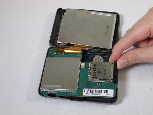
Using the plastic opening tool, push apart the clasps holding the LCD screen in place.
-
Wedge the plastic opening tool between the LCD screen and the metal frame of the device.
-
-
-
Cette étape n’est pas traduite. Aidez à la traduire
-
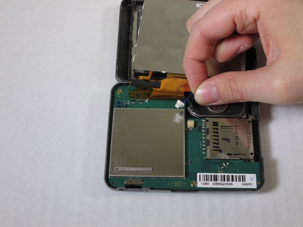
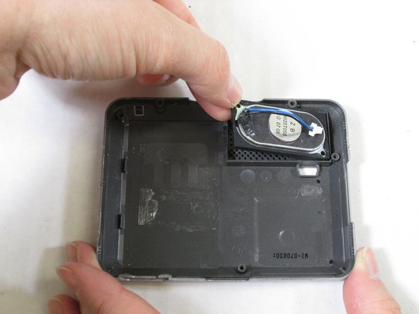
Hold the blue wire from its connector head.
-
Pull the connector head out of the outlet to unplug the speaker.
-
-
Cette étape n’est pas traduite. Aidez à la traduire
-
Using the Phillips #PH00 screwdriver remove the three screws that hold the motherboard in place.
-
Use Screwdriver bit #PH00 in IFixIt's Tool Kit to take out the three screws holding the motherboard in place.
-
-
Cette étape n’est pas traduite. Aidez à la traduire
-
Peel the strip of orange tape from the white attachment bar on the motherboard.
-
This detaches the motherboard and LCD Screen (see second picture for blue box).
-
-
Cette étape n’est pas traduite. Aidez à la traduire
-
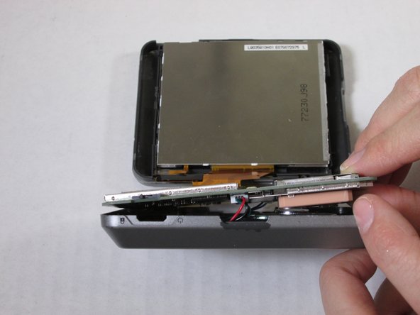
Remove the strip of orange tape from the LCD screen to detach the LCD screen from the front casing.
-
-
Cette étape n’est pas traduite. Aidez à la traduire
-
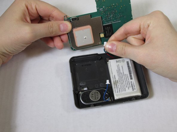
Prop the motherboard up.
-
Hold the red and green wires from the connector head.
-
Pull the connector head out of the outlet to detach the motherboard from the back casing.
-
-
Cette étape n’est pas traduite. Aidez à la traduire
-
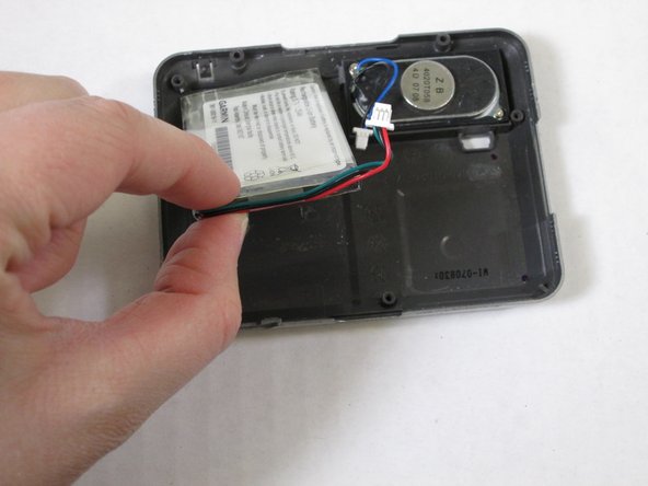
Use care. The back casing and battery are glued together. Do not puncture the battery.
-
Push the flat end of the spudger under the battery and separate the battery from the back casing.
-
-
Cette étape n’est pas traduite. Aidez à la traduire
-
Using the Phillips #000 screwdriver remove the two screws holding the speaker in place.
-
Remove the speaker.
-


Équipe

University of Maine, Team 1-11, Diaz Fall 2013 Membre de l'équipe University of Maine, Team 1-11, Diaz Fall 2013
UMAINE-DIAZ-F13S1G11
2 membres
1 tutoriel rédigé