Cette version peut contenir des modifications incorrectes. Passez au dernier aperçu vérifié.
Ce dont vous avez besoin
-
Cette étape n’est pas traduite. Aidez à la traduire
-
Turn the device over and remove the 4 x T5 screws.
-
-
Cette étape n’est pas traduite. Aidez à la traduire
-
Use the prying tool to release the platic clips on the back, going around all the sides.
-
Start prying from the sides or the top left corner and work your way around the screen.
-
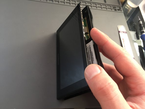
Slide the screen slightly upwards to reveal the connector
-
-
Cette étape n’est pas traduite. Aidez à la traduire
-
Slide up the screen to get access to the connector
-
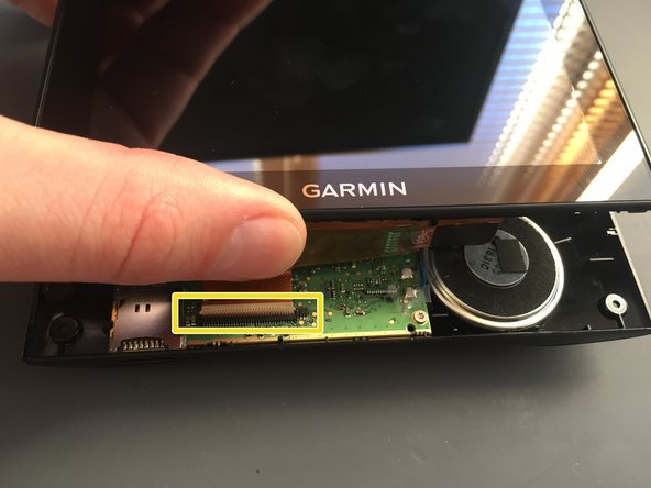
Use the plastic prying tool to lift up the latch that secures the ribbon cable and then slide the cable out.
-
Once the cable is out, lift off the screen.
-
-
-
Cette étape n’est pas traduite. Aidez à la traduire
-
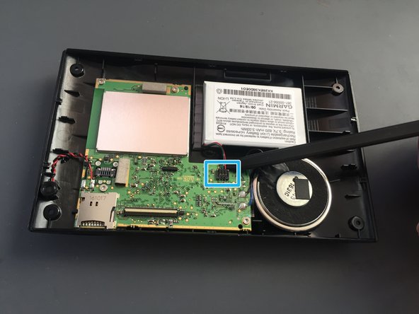
Before you can take the logic board out disconnect the battery.
-
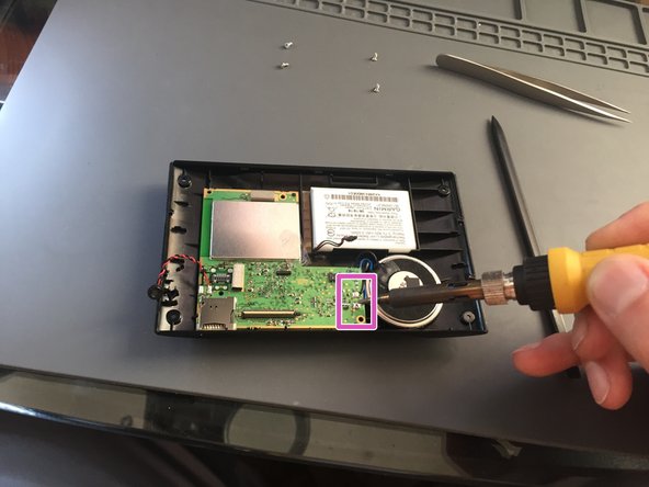
Remove the microphone from its socket with a plastic spudger.
-
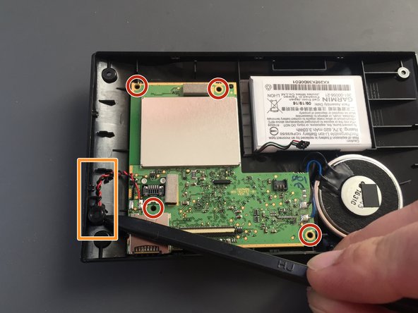
Remove the 4 x T5 screws that secures the logic board to the back cover.
-
-
Cette étape n’est pas traduite. Aidez à la traduire
-
Peel off the clear tape from the speaker connections with tweezers.
-
Use your soldering iron to de-solder the two wires from the speaker.
-
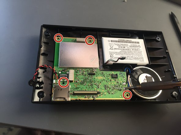
Finally remove the 4 x T5 screws that secure the logic board to the back cover.
-
-
Cette étape n’est pas traduite. Aidez à la traduire
-
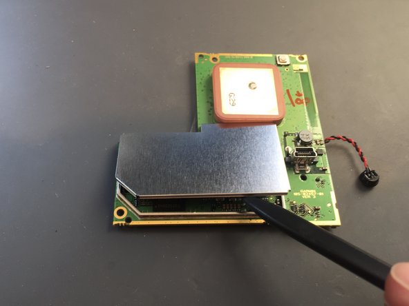
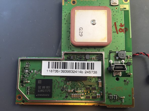
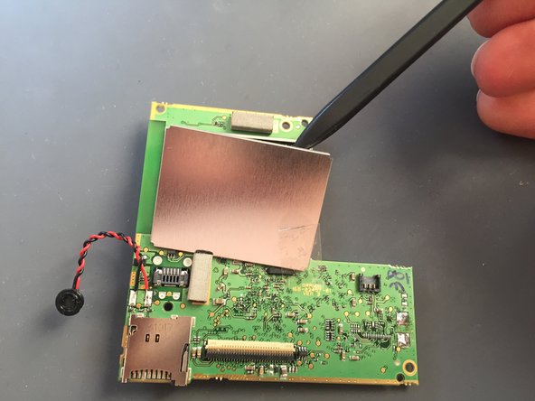
To reveal all the components, use the spudger to lift off the metal cover of the protected circuitry
-
-
Cette étape n’est pas traduite. Aidez à la traduire
-
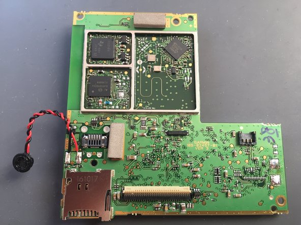
Repeat the same step on the back of the logic board.
-
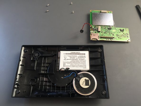
Now you successfully exposed all the parts.
-


Annulation : je n'ai pas terminé ce tutoriel.
Une autre personne a terminé cette réparation.
