Cette version peut contenir des modifications incorrectes. Passez au dernier aperçu vérifié.
Ce dont vous avez besoin
-
Cette étape n’est pas traduite. Aidez à la traduire
-
Insert a SIM card eject tool or a paperclip into the small hole in the SIM card tray, located on the left edge of the phone, opposite of the power and volume buttons.
-
Press firmly to eject the tray.
-
-
Étape 3 Procédure d'ouverture
Attention : les étapes 3 à 14 sont issues d'un tutoriel marqué comme en cours.
-
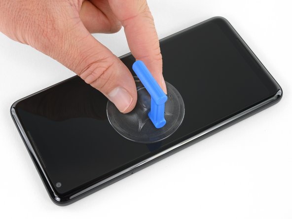
Posez une ventouse le plus proche possible du bord côté fente SIM en évitant la partie incurvée.
Shouldn’t this be “As close as possible to the volume rocker”?
Forget about the tiny toy suction cup they provide to battery replacement kits. I used a dent puller from an automotive shop. The smallest they had was just small enough for the Pixel's screen. I still needed to heat the edges with a heat gun.
I wish someone tell me in advance that if I doing this replacement after using phone for a few years it better to have spare "display adhesive" and be ready to follow Google Pixel 2 XL Display Adhesive Replacement
Original adhesive become dirty with time and fat chances it will be damaged during opening phase. In my case I replaced battery but can't use the phone, as still waiting for adhesive to be delivered -
-
-
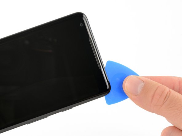
Tirez fermement et constamment sur la ventouse et insérez un médiator entre le panneau frontal et la coque arrière.
Whatever happened to “Do not heat your phone. If needed, you can use a dropper or syringe to inject isopropyl alcohol (90+%) around the edges of the back cover to weaken the adhesive.”?
It is in concern with swollen batteries.
I spent an hour trying to get the glass screen apart from the body. I tried the hairdryer etc but made no progress. However, when I used a sucker to gently pull on the glass it was easy.
I used a heat gun, and the metal spatula in the iFixit kit. I broke the screen. Then, continuing with a blue plastic triangle, the screen continued to break. It seems to be quite brittle.
Never use metal tools on glass component
p43j77 -
Just broke the screen as well. I’d say heat gun is a must, otherwise it’s really hard to slide pick at the top and bottom without breaking the screen. It’s a very thin line of glass over there.
I thought I did this perfectly. I used the iOpener to heat the glue, and the picks to slide around the screen to release the adhesive. I preformed the rest of the repair (charging assembly and the battery) with little issue. Just reassembled and the volume rocker side of the screen is white. I took less care on this side since the instructions said that you didn’t need to worry about how far the pick went in. NOT TRUE! There is a curvature to that edge that will push your pick up into the back of the unprotected display. It clearly doesn’t take much to damage it. I was so careful! F&CK!! I should have just created the e-waste and bought a new device. So mad!
-
-
-
N'insérez pas le médiator de plus de 6 mm (0,25") dans le bord inférieur du téléphone. Si votre outil touche la partie repliée de la dalle OLED, cela risque d'abîmer l'écran.
-
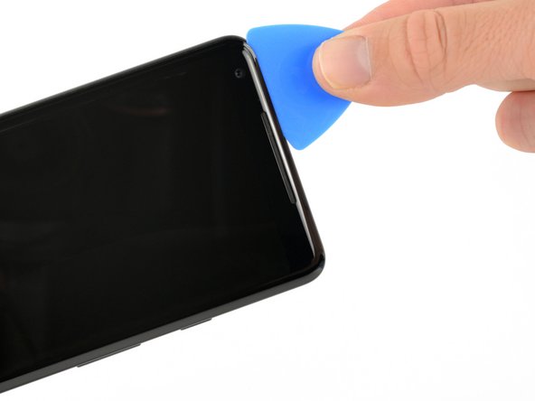
Ne coupez pas le long du bord gauche, vous pourriez endommager les nappes de l'écran, qui sont fragiles.
-
Faites des découpes peu profondes dans le coin supérieur gauche pour éviter la caméra frontale.
-
-
-
-
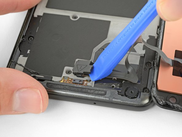
Servez-vous du coin d'un outil d'ouverture pour faire levier sur le cache du connecteur de la nappe de la vitre tactile.
-
Retirez le cache du connecteur.
Lol mine shot off and Ricocheted off the ceiling! Then landed on my shoulder haha
It literally popped me right in the middle of the forehead. My wife is still making fun of me.
Mine flew off while I was laughing you guys, never too be seen again: (
I decided to work outdoors, didn't read any comments first, so when mine flew off I found it five cursing minutes later in a crack on the driveway. Should have read the comments first! Thanks hamiltont. Will now read every comment BEFORE attempting step.
Confirmed, this $@$* can fly!
-
-
-
Prenez la pointe d'une spatule (spudger) pour soulever le connecteur de la nappe de la vitre tactile vers le haut et hors de sa prise sur la carte mère.
This small connector gave me fits getting it located correctly, is there a trick to getting it aligned since it’s difficult to see around edge of the connector?
-
-
-
Prenez l'extrémité plate d'une spatule pour débrancher le connecteur de la nappe de l'écran de sa prise.
-
Enlevez l'écran.
BE EXTRA CAREFUL HERE, and during reassembly! There are 2 itty bitty parts directly under this ribbon cable connector that, if damaged, will render your loudspeaker unusable. The only sure way to fix it if you break it is to replace the motherboard. There are some reports of people being able to solder the spots and shorting it to make it work, and that worked for me for a time, but they’re really tiny (about 0.5 mm) and if you don’t get a secure solder, or if you bleed over, it will also mess up your top speaker.
Saw this comment after I’ve done replacing and sure enough, the loud speaker was broken. The resistor was knocked over but still hanging in place so I just stuck it back and it works for now.
They are 2 black resistors at the end of the cable’s connector. So follow the above photo exactly and pry the connector from the side, not from the end of the connector like I did
What wasn't clear to me here (because I didn't put Step 13 together with Step 12, I suppose?) is that if your replacement part came with speaker grills and camera gasket, Step 12 is your final step. You are done, except for replacing the cables and covers, then placing the adhesive strips onto the replacement part and sticking the phone back together.
I ordered my screen from iFixit and it came with new grills and camera gasket already installed. I was able to use the thinnest strips on the supplied Tesa patch to line the entire screen perimeter piecemeal, then stick it back together like new.
-
-
-
Dévissez les onze vis cruciformes de 3,8 mm qui fixent le châssis central.
-
-
-
Insérez un outil d'ouverture dans l'encoche du châssis central, à côté des boutons de volume et soulevez le châssis central vers le haut pour l'écarter du téléphone.
-
Retirez le châssis central.
How do I reattach the midframe? it seems like there are a lot of tabs that need to be reinserted carefully
Slide in the bottom part at an angle in first since it has some tabs. Otherwise it will get stuck halfway on top
-
-
-
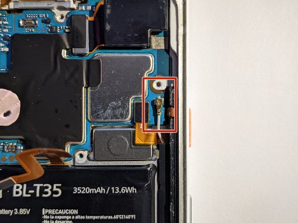
Prenez l'extrémité plate d'une spatule pour débrancher le connecteur de la batterie.
-
-
Cette étape n’est pas traduite. Aidez à la traduire
-
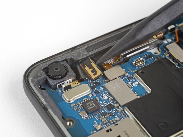
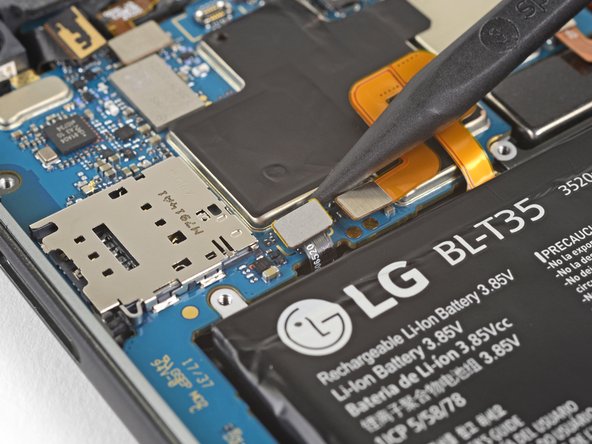
Use the point of a spudger to disconnect the front-facing camera connector.
-
-
Cette étape n’est pas traduite. Aidez à la traduire
-
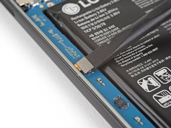
Use the flat end of a spudger to disconnect the right Active Edge sensor connector.
-
Disconnect the antenna cable.
Also disconnect the antenna cable just to the right of the right Active Edge sensor connector
-
-
Cette étape n’est pas traduite. Aidez à la traduire
-
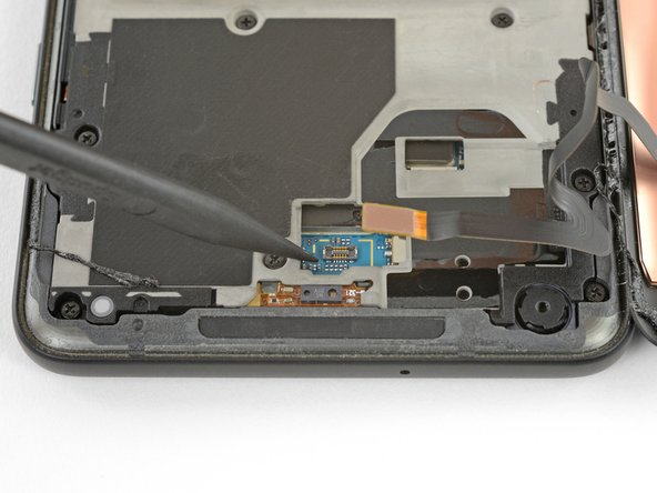
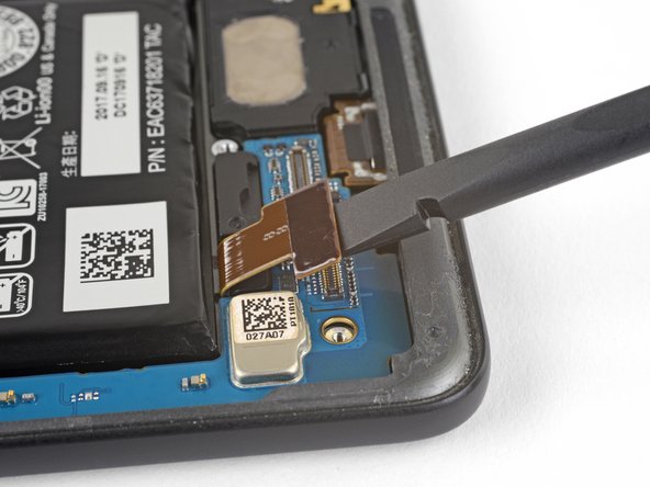
Use the point of a spudger to disconnect the fingerprint sensor connector.
-
-
Cette étape n’est pas traduite. Aidez à la traduire
-
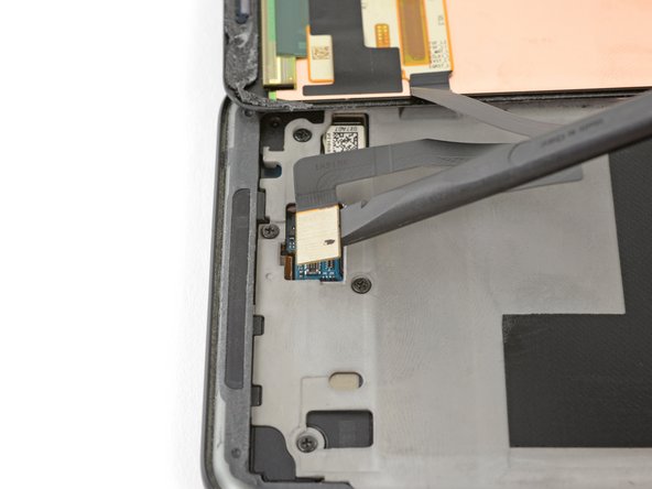
Use the flat end of a spudger to disconnect the left Active Edge sensor connector.
-
-
Cette étape n’est pas traduite. Aidez à la traduire
-
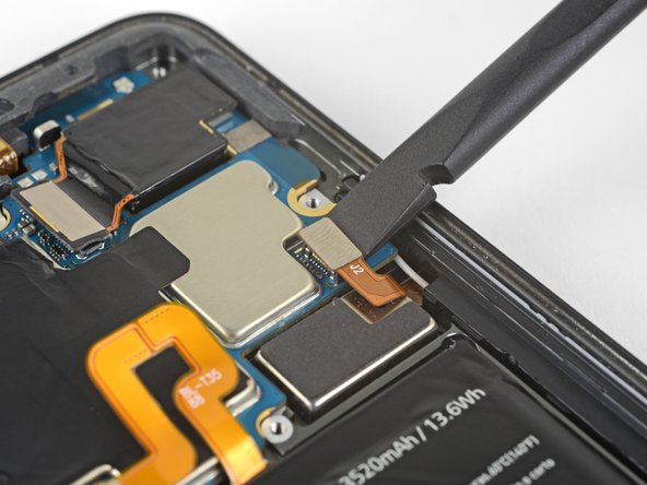
Use the flat end of a spudger to disconnect the charging assembly connector.
-
-
Cette étape n’est pas traduite. Aidez à la traduire
-
Use the point of a spudger to disconnect the front-facing sensor assembly connector.
-
-
Cette étape n’est pas traduite. Aidez à la traduire
-
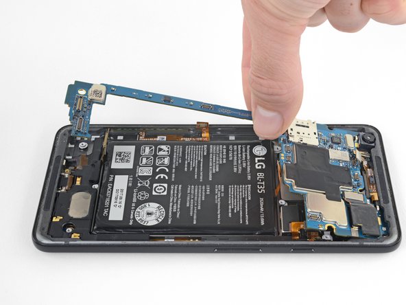
Make sure all the cables and connectors are clear of the board, and use the flat edge of a spudger to gently lift the bottom of the motherboard.
-
Holding the wide part of the motherboard near the SIM card slot, carefully slide the board toward the bottom of the phone while lifting it out of the phone.
-
Remove the motherboard.
-
Try to keep the phone flat with the battery facing up after you remove the motherboard, as the front-facing camera can fall out of the phone case very easily.
Agreed. No mention of the antenna cable.
-
-
Cette étape n’est pas traduite. Aidez à la traduire
-
Slide the point of a spudger under the lower left side of the loudspeaker and slowly pry the speaker assembly up from the phone.
This step was very difficult, I believe I just snapped the loudspeaker to the left of silver oval piece
I was just able to remove the loud speaker using the directions provided. The piece sprung out of the phone. The bottom of the piece is flat with pieces of metal and it appears to be slightly bent from my prying. We will see if it still works.
I ended up using my metal silver spudger. It goes in farther without prying on the fragile plastic. I’m replacing the charging circuit anyway, so not too worried about minor damage
This is a difficult step. Pictures indicating other safe pry points would be helpful.
Most stubborn component to remove.
I was able to remove this without great stress on the part by inserting my right thumbnail (thumbprint facing the battery / top of the phone) in between the loudspeaker and the phone body above the silver oval, while at the same time using my left index fingernail to gently lift the long left side protrusion of the loudspeaker. Note that the plastic opening picks were too thick for this. Took twenty minutes or more to figure this out, but about two minutes or less to do it. The fundamental problem seems to be that this part is friction-fit into place, and you won’t get it out all in one motion without risk of breaking it, you have to work at it alternately from every angle. I also added a few drops of everclear (95% ethanol, isopropyl was hard to come by because of COVID), which may or may not have mattered (I have no control for this experiment). I believe there was no damage to the part.
-


Annulation : je n'ai pas terminé ce tutoriel.
7 autres ont terminé cette réparation.

2 commentaires
Does this method work with the earpiece one as well?
We don’t have official instructions out for the earpiece speaker, but it’s only accessible underneath the glass panel and antenna assembly on the back of the phone so removing it is a bit different. After removing the motherboard you would have to lift this flex cable from the back of the phone, just enough to separate it from the adhesive holding it down. Then you can carefully pry up the glass panel, and remove antenna assembly and the earpiece speaker underneath. You’ll probably need an iOpener, suction cup, and opening picks to remove the panel and everything underneath—they’re all glued down pretty solidly.