Introduction
This repair guide was authored by the iFixit staff and hasn’t been endorsed by Google. Learn more about our repair guides here.
Follow this guide to replace the rear-facing camera on a Google Pixel 4a.
The unreinforced display panel on the Pixel 4a is fragile. Pay special attention to the warnings in the opening procedure if you are reusing the screen.
Ce dont vous avez besoin
-
-
Insert a SIM eject tool, bit, or straightened paper clip into the SIM tray hole.
-
Press directly into the hole to eject the SIM card tray.
-
Remove the SIM card tray.
-
-
-
Take note of the two seams on the edge of the phone:
-
Screen seam: This seam separates the screen from the rest of the phone. This is where you should pry.
-
Frame seam: This is where the plastic frame meets the back cover. It is held in place by screws. Do not pry at this seam.
-
Before you begin, note the following areas on the screen:
-
Screen flex cable: Do not insert the opening pick deeper than instructed or you risk damaging this cable.
-
Adhesive perimeter: Prying beyond this narrow perimeter without angling the pick will damage the OLED panel.
Coll down guys and gals.
1) go below the Display and not between the backcover/middle (see the other comments)
2) just take care about the flex/display cable position (which is iirc about on the middle i.e. 2nd 3rd from the bottom ON THE LEFT side dear OP)
Everything else is just separting the glued on Display from the Phone.
See the other comments
Cool down guys and gals.
1) go below the Display and not between the backcover/middle (see the other comments)
2) just take care about the flex/display cable position (which is iirc about on the middle i.e. 2nd 3rd from the bottom ON THE LEFT side dear OP)
Everything else is just separting the glued on Display from the Phone.
See the other comments
I've measured it: The cable starts arround 1.4-1.6 cm from the lower half from the bottom on the left side.
So You can cut the bottom left corner and of course the upper left one but for safety's sake, watch out for the camera.
You can go up to 5cm down from the upper left side till You're near the cable.
When you say left side, is this your left when the phone screen is facing you?
jaunie -
The third image her shows the back of the screen, not the body of the phone
-
-
-
Apply a heated iOpener to the right edge of the display for one minute to soften the adhesive.
-
-
-
Place a suction cup as close to the right edge of the screen as possible.
-
Lift the suction cup with a strong steady force.
-
Insert the tip of an opening pick into the screen seam no more than 1 mm.
It's pretty easy. Insert it just below the screen between the Display and the Display “holder” or mold.
-
-
-
With the pick 1 mm into the gap, pivot the pick upwards to a steep angle.
-
At a steep angle, carefully push the pick into the gap about 1/4 inch (6 mm). The pick should slide in below the OLED panel.
This took me a while, I ended up sharpening the tip of the pick with a razor so I could push it through the seam and slicing a few times, heat->sharpen-> slice until I finally got it to move, and once it slid under carefully heated up areas and sliced with ~2mm of the pick.
This sounds also harder than it is. Push it in 1mm and just lift the other end in a wider angle like 70° degree from the horinzontal position. There “shouldn't” be much you can do wrong. Because except for the Data cable (flex) at a certain position, I can't remeber anything important but isolating tapes that I have scratched.
It's just the Screen glued to the mold. That's it.
Oh, and I wonder here where do You all get such thins plectrums? I have also the flat plastic version and the thin plastic cards but none of them were thin enough for this!!
I ended up using the backside i.e. the dull side of a Razorblade. I didn't saw any alternatives to this. Did You hear this OP?
Any!!
the display flex is directly on the bottom of the phone. BE VERY CAREFUL when going around the bottom to not hit the display flex!!!
-
-
-
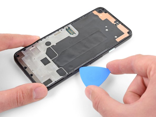
Slide the pick along the right edge of the screen to cut the adhesive.
-
Leave the pick in the top right corner to prevent the adhesive from re-sealing.
The display flex is directly on the bottom of the phone. Be very careful when goign around the bottom to not hit the display flex!!!
-
-
-
Insert another opening pick into the right edge of the phone at an angle where a gap has already formed to prevent damage to the OLED panel.
-
Slide the opening pick around the bottom of the phone to cut the adhesive.
-
Leave the pick inserted along the bottom edge to prevent the adhesive from resealing.
Top and bottom edge adhesive were much stronger than this suggests. Corners were very hard to detach. I killed my screen b/c I cracked it at the top. Worked better with heating around whole perimeter like an iPhone.
WARNING: Be very careful prying the bottom left and right corners! In fact do not insert anything there because there is only a 0.8mm clearance between the screen and the edge, and there's a 0.5mm space between the screen and front glass where if you insert a pick between the screen will crack and break! I had to replace the screen after only doing a battery repair...
Unfortunately I did not properly read the comments here. So for the unafraid people like me:
DO NOT insert something into the bottom right! Especially not like it is shown in the image at this location!
Instead I suggest start releasing the screen from right, then left side, then top and as the last step release the bottom, but start with the left corner. Do not pry too much and use a bit more heat as suggested.
There is a small image of this critical right corner in Step 16 (the part at the top is the display and the left corner at the top is the critical right corner here). You'll see the orange cable in the corner which is easy to damage...
I can second the warnings - especially at the lower corners the OLED screen is extremely sensitive to breaking - as has happened in my attempt when inserting the pick 2 mm.
The display flex is directly on the bottom of the phone. Be very careful when goign around the bottom to not hit the display flex!!!
-
-
-
Insert another opening pick into the bottom edge of the phone at an angle where a gap has already formed to prevent damage to the OLED panel.
-
Use the pick to slice through the left edge of the phone.
-
Leave the pick inserted along the left edge of the phone to prevent the adhesive from re-sealing.
The display flex is directly on the bottom of the phone. Be very careful when goign around the bottom to not hit the display flex!!!
-
-
-
Insert another opening pick into the left edge of the phone at an angle where a gap has already formed to prevent damage to the OLED panel.
-
Slide the pick around the top edge of the phone to cut the adhesive.
The display flex is directly on the bottom of the phone. Be very careful when goign around the bottom to not hit the display flex!!!
-
-
-
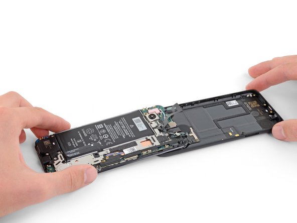
Lift from the top edge and swing the screen over the bottom edge until you can rest it glass-side down.
FR : Précision : La nappe a un bout d'adhésif sur la structure du téléphone, il faut bien faire attention de le décoller. Je viens de tuer la nappe de mon écran qui était fonctionnel...
EN : Advice : The ribbon cable is fixed to the structure with a small piece of adhesive. It should be remove prior to anything else. I just killed the ribbon cable of my perfectly used to work screen...
-
-
-
Use a pair of tweezers to carefully peel up the black tape covering the screen connector bracket.
Interestingly this tape was missing in my phone. Maybe that explains some of the display issues I occasionally had, like a thin green line on the right side of the screen which could be "pushed" away.
I think I ripped off the cable because it is undistinguishable from the tape! How screwed am I?
-
-
-
Use a T3 Torx driver to remove the two 2.1 mm screws securing the screen connector bracket.
A T4 driver worked for me here.
It is definitely a T4.
Funny ... For me, it was T3. The screws must vary across different phones
-
-
-
-
Use the tip of a spudger to pry up and disconnect the screen flex cable.
No, why the tip? Use the other flat side that doesn't concetrate all the power on one point and Youre doing a propper job.
Only the tip is needed to lift a bit one of the sides and it will pop out. No pressure/power!
-
-
-
Remove the screen.
-
Check if your replacement screen has speaker mesh and top edge adhesive pre-installed.
-
If it does, you won't need the top edge adhesive.
-
If it doesn't, remove the larger clear liner from the top edge adhesive and apply it to the screen (not the frame). Make sure the larger cutout lines up with the speaker mesh.
-
Follow this guide to apply the custom-cut adhesive.
This step seems to imply that a screen replacement is necessary when replacing the charging port. Is the charging port replaceable without replacing the screen? I understand great care must be taken not to damage the original screen in the procedure, but can it be reinstalled?
Yes, it can be reinstalled.
Just a heads up: If you are like me and you have accidentally turned on your Pixel 4a at some point while trying to pry the screen, don't worry too much. I was able to just connect my display with the device on. Nothing will happen until you reboot, and then the screen will initialize.
It would help to add that the new screen is reattached after adding glue to phone body, not the screen. With the iFixit screen adhesive pieces, a guide to which piece goes where would help also. For that I used this picture: Google Pixel 4a Display Adhesive - Genuine. Yet that is not enough as there is a cover for (speaker?) which is not clear how to apply that.
The repair kit comes with Google Pixel 4a Display Adhesive - Genuine but there is no guide on how to apply that adhesive. I sent an email, but Ifixit won't make an instruction page for this.
To explain how the adhesive sold by iFixit works, the actual adhesive is the black strip which is held between two pieces of plastic. Line up the pieces with the clear plastic side down. Note that some pieces may be stuck in the box they came in, the plastic is staticky. I recommend that before attaching the new screen you put each piece in place. Remove the clear plastic and place the pieces in place with the colored plastic facing up. The goal is to have the black adhesive strip on the little ledge between the edge and the depression inside the phone. It's the place where you hopefully spent time cleaning out the original adhesive. Place the corners first, then the edges. Press them into place carefully. Before removing the colored plastic attach the phone screen cable and secure it. REMEMBER TO PLACE THE ELECTRICAL TAPE OVER THE CONNECTOR (I forgot to). Then remove the colored plastic, leaving behind the adhesive, and push the screen into place.
Of note: the seal peace at the top goes under the speaker screen, and the seal looks at first like it is reversed. To install that one accurately adhere it to the Screen itself not the body of the phone. align it where there is a see through circle along the seam and a hole in the adhesive. the sealant should run below the speaker screen. When readhering the screen to the body, remove the plastic guides around the body, then last the seal on the screen and align and install.
Super, c'est vraiment à la portée de tout le monde, il faut juste un peu de patience et d'audace.
Je viens de réussir le remplacement de mon écran et c'est impec !
Il n'y a que sur la première partie, où il faut insérer le médiateur, que ça a été compliqué pour moi. Impossible de l'insérer du côté des boutons (à droite donc), par contre quand je me suis décidée à tester en passant par l'autre côté, c'est venu tout seul.
Aussi il m'a fallu un certain temps pour comprendre que sur les adhésifs, seul le trait noir colle, et c'est donc à lui qu'il faut faire attention.
Pensez à vérifier que l'écran est fonctionnel avant de le recoller, à mon premier essai la nappe n'était pas bien insérée et j'ai du recommencer l'insertion. Voila, prendre son temps et vérifier que tout va bien à chaque étape et c'est très facile. J'ai mis un peu moins d'une heure.
After I clipped the screen in place, I realized that I had forgotten to reattach the screen bracket from step 14. Do you think this is dangerous? Can anyone assess this? In any case, the smartphone turns on and actually makes a good impression.
Many thanks in advance for your assessment!
Kind regards
Tom
Just some advice before you install the screen regarding the earphone grille/mesh at the top.
Something I experienced, was that the speaker grille did not end up being seated quite right when the phone display was stuck down. It is slightly bent, and the top edge is stuck out at a slight angle - it is quite sharp and does not take much to catch a finger on it, when the phone is out of a protective case.
I think this was because I laid the screen in, starting from the top and with it up at quite a steep angle, then working from top to bottom. I would suggest that when setting the new display within the device, that you align the bottom edge first instead.
I am not going to risk lifting the new display to try and re-seat this grille properly, the display cost me a bloody fortune (around 58% of the phone's original price) and I am not risking breaking it over something as minor as that.
nb. I definitely removed all the coloured plastic protective pieces before installing the new screen into the phone.
-
-
-
Use a T3 Torx driver to remove the eight 4.3 mm screws securing the back cover to the midframe.
-
-
-
Insert an opening pick into the seam between the midframe and the back cover.
-
Slide the opening pick along the bottom edge of the phone to release the plastic clips securing the back cover to the midframe.
-
-
-
Use a T3 Torx driver to remove the seven screws securing the motherboard bracket:
-
Three 2.9 mm-long black screws
-
Three 2 mm-long screws
-
One 4.1 mm-long screw
-
-
-
Use the tip of a spudger to unclip the motherboard bracket from the upper-right and lower-right corners of the motherboard.
on mine, the fingerprint sensor cable was lightly adherent to the bracket and I almost tore it when the bracket popped up. may want to add something about freeing this up before removing the bracket.
Similar to Erik, my fingerprint sensor cable was adhered to the bracket and mine did tear. I didn't use the fingerprint sensor, so hopefully this doesn't affect anything else with the phone. Now I know to read the comments! X_X
I had the same issues: The cable was attached to the bracket and I had to be very careful in pushing the bracket to the side and reach under it with the spudger to detach the fingerprint cable. And I also found the top clip of the bracket hard to unclip. It worked when I started with the lower one and then pushed the bracket to the side a bit. It seemed to be glued on the top corner.
My fingerprint sensor cable was also glued to the bracket, but it seems like a sturdy cable so was not easily damaged
Ok this was really bad for me I did not understand how the clip was oriented and tried to pull it up lightly first and then strongly, it finally came off but I bent and broke the bridge just a bit, and most importantly the RFID or fingerprint sensor cable (the circle in the back). I don't use it and nothing more was harmed managed to put everything back in place but
Beware of the clips, you have to pull them TOWARDS you, then the bridge will pop-up, don't apply strength upwards before unclicking the 2 clicks towards you (horizontal plane)this is the most frustrating step in the entire guide. i used tweezers and pushed to the left of the upper bracket to free it. no upward force is required to free it. be careful
-
-
-
Use the flat end of a spudger to pry up and disconnect the battery cable.
-
-
-
Use the tip of a spudger to disconnect the two flex cables connecting the fingerprint sensor and buttons to the motherboard.
-
-
-
Use the tip of a spudger to disconnect the headphone jack cable from the motherboard.
-
-
-
Insert an opening pick under the headphone jack and twist to release it from the adhesive securing it to the midframe.
-
Remove the headphone jack.
There shouldn't be a need to remove the headphone jack to get to the charging port since you have already disconnected it from the board.
I did not remove the microphone jack as you suggested and it was fine, thanks!
IFuxedIt -
I also tried skipping the step but then trapped the cable under the motherboard on reassembly. I would say for that reason that it's safer to fully remove.
-
-
-
Pry up with the flat end of a spudger to disconnect the front-facing camera from the motherboard.
-
-
-
Use a T3 Torx driver to remove the two 4.1 mm screws securing the loudspeaker assembly.
-
-
-
Use the tip of a spudger to disconnect the loudspeaker cable from the motherboard.
Be careful on this step. I ended up popping out part of the clip housing (I may be able to repair once I look at it with a magnifying glass). Maybe the flat side of the spudger would be better.
-
-
-
Use a T3 Torx driver to remove the three screws securing the motherboard:
-
Two 2.9 mm-long black screws
-
One 2.1 mm-long screw
-
-
-
Use the corner of an opening pick to peel up the tape covering the earpiece speaker.
-
-
-
Insert the tip of a spudger underneath the bottom edge of the motherboard and pry it up enough to grip it with your fingers.
-
-
-
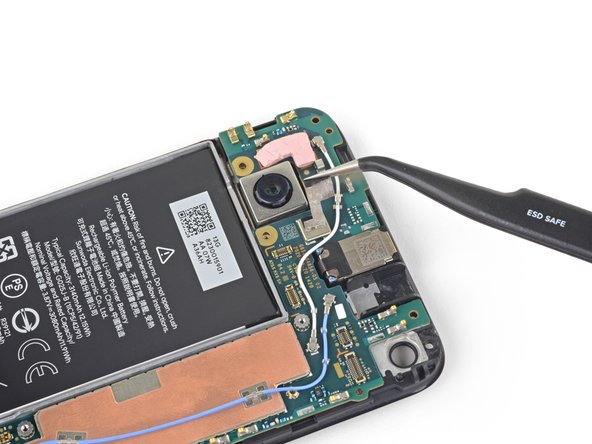
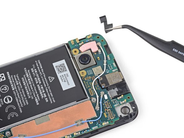
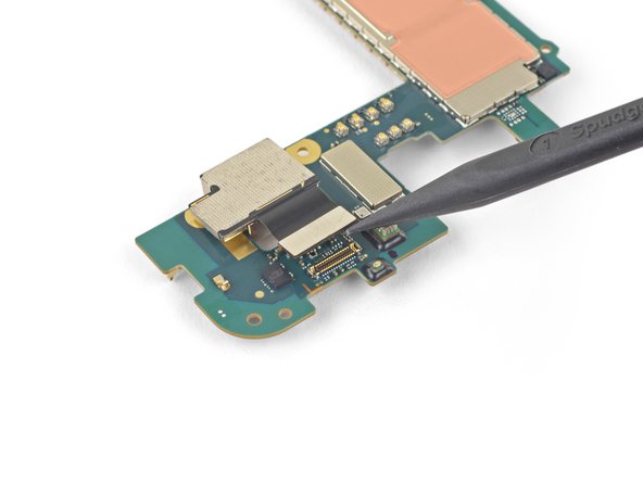
Use the tip of a spudger to disconnect the rear-facing camera from the motherboard.
-
Remove the rear-facing camera.
-


To reassemble your device, follow the above steps in reverse order.
Take your e-waste to an R2 or e-Stewards certified recycler.
Repair didn’t go as planned? Try some basic troubleshooting, or ask our Answers community for help.
To reassemble your device, follow the above steps in reverse order.
Take your e-waste to an R2 or e-Stewards certified recycler.
Repair didn’t go as planned? Try some basic troubleshooting, or ask our Answers community for help.
Annulation : je n'ai pas terminé ce tutoriel.
2 autres ont terminé cette réparation.
