Cette version peut contenir des modifications incorrectes. Passez au dernier aperçu vérifié.
Ce dont vous avez besoin
-
Cette étape n’est pas traduite. Aidez à la traduire
-
With the case closed, place the Mini 1000 top-side down on a flat surface.
-
Push both of the battery release latches toward each other.
-
-
Cette étape n’est pas traduite. Aidez à la traduire
-
Lift the battery out of the Mini 1000 from the edge closest to the release latches.
-
-
Cette étape n’est pas traduite. Aidez à la traduire
-
Remove the following two screws:
-
One 6 mm Phillips screw
-
One 4 mm Phillips screw
-
-
Cette étape n’est pas traduite. Aidez à la traduire
-
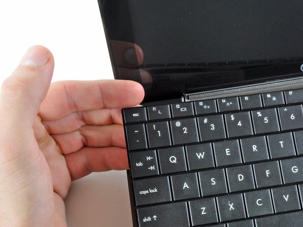
While pushing through the opening with one hand, grasp the left upper edge with the other hand and slightly pull the keyboard towards you.
-
Once an opening has been established, grasp the keyboard and slowly lift it upwards along the upper perimeter of the top edge.
-
-
Cette étape n’est pas traduite. Aidez à la traduire
-
Lift the keyboard out of the upper case, minding the cable that is still connecting it to the motherboard.
-
-
Cette étape n’est pas traduite. Aidez à la traduire
-
Use your fingernail or the flat end of a spudger to flip up the retaining flap on the keyboard cable ZIF socket.
-
Pull the cable out of its socket and remove the keyboard.
-
-
Cette étape n’est pas traduite. Aidez à la traduire
-
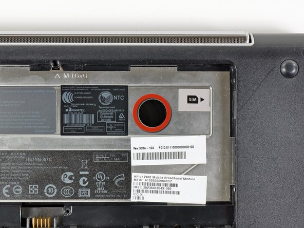
Use your fingernail or the flat end of a spudger to flip up the retaining flap on the SIM card ribbon cable ZIF socket.
-
Pull the SIM card ribbon cable out of its socket and peel it off the top of the hard drive enclosure.
-
-
-
Cette étape n’est pas traduite. Aidez à la traduire
-
Use your fingernail or the flat end of a spudger to flip up the retaining flap on the hard drive cable ZIF socket.
-
-
Cette étape n’est pas traduite. Aidez à la traduire
-
Remove the two 4.5 mm Phillips screws securing the hard drive to the lower case.
-
-
Cette étape n’est pas traduite. Aidez à la traduire
-
Lift the hard drive up and out of the lower case, being careful not to damage its cable in the process.
-
-
Cette étape n’est pas traduite. Aidez à la traduire
-
Using the sharp tip of a spudger, pry and remove the four plastic screw covers from the underside of the HP Mini 1000.
-
The two bottom covers are short in height and are notched to prevent incorrect insertion
-
The upper right cover is taller in height and is notched.
-
The upper left cover is taller in height and is not notched.
-
-
Cette étape n’est pas traduite. Aidez à la traduire
-
Remove the four 7 mm Phillips screws that secure the upper case to the lower case.
-
-
Cette étape n’est pas traduite. Aidez à la traduire
-
Flip the computer over and open the display.
-
Remove the two 4.5 mm Phillips screws securing the upper case to the lower case.
-
-
Cette étape n’est pas traduite. Aidez à la traduire
-
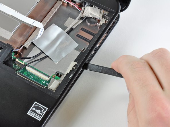
Wedge the flat end of a spudger in between the upper case and lower case near the bottom right corner of the display.
-
Carefully pry and rock the spudger upwards to create a small gap between the upper case and lower case.
-
Continue the previously described motion along the right edge of the upper case to release the clips securing the upper case to the lower case.
-
-
Cette étape n’est pas traduite. Aidez à la traduire
-
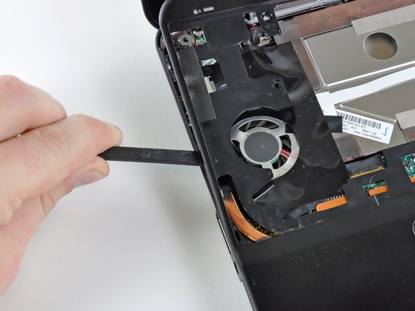
Repeat the same procedure as mentioned in the previous step to release the clips along the left side of the upper case.
-
-
Cette étape n’est pas traduite. Aidez à la traduire
-
Grasp the upper case and carefully lift it slightly upwards, freeing it from any remaining clips.
-
-
Cette étape n’est pas traduite. Aidez à la traduire
-
Use your fingernail or the flat end of a spudger to flip up the retaining flap on the TouchPad cable ZIF socket.
-
Pull the TouchPad ribbon cable out of its socket.
-
Remove the upper case from the HP Mini 1000.
-
-
Cette étape n’est pas traduite. Aidez à la traduire
-
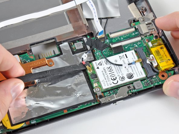
Pry the WWAN antenna connectors (2 total) up off the WWAN board.
-
-
Cette étape n’est pas traduite. Aidez à la traduire
-
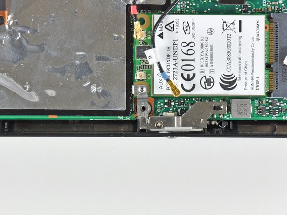
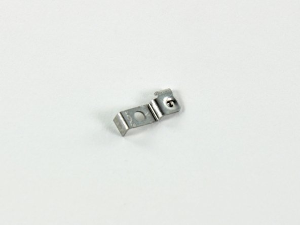
Remove the single 3 mm Phillips screw securing the WWAN metal bracket and WWAN board to the motherboard.
-
-
Cette étape n’est pas traduite. Aidez à la traduire
-
Grasp the WWAN board and pull it straight out of its socket on the motherboard.
-


Annulation : je n'ai pas terminé ce tutoriel.
2 autres ont terminé cette réparation.
