Cette version peut contenir des modifications incorrectes. Passez au dernier aperçu vérifié.
Ce dont vous avez besoin
-
Cette étape n’est pas traduite. Aidez à la traduire
-
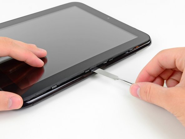
In the following steps, you will use a metal spudger to lift the front panel out from the rear case of your TouchPad.
-
-
Cette étape n’est pas traduite. Aidez à la traduire
-
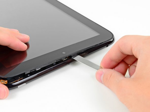
Insert a flat metal spudger in the gap between the rubber outer ring on the front panel assembly and the black plastic rear case near the USB connector.
-
Pry the front panel assembly up from the rear case, being careful not to damage the LCD or the glass panel.
-
-
Cette étape n’est pas traduite. Aidez à la traduire
-
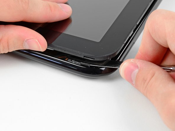
As in the previous step, use a spudger to pry the front panel up from the rear case along its long edge on the volume button side of the TouchPad.
-
Continue to pry the front panel assembly up along the volume button side of the TouchPad until there is a gap between it and the rear case.
-
-
Cette étape n’est pas traduite. Aidez à la traduire
-
Pry up the front panel assembly along the top edge of the TouchPad.
-
-
-
Cette étape n’est pas traduite. Aidez à la traduire
-
Pry up the front panel along the edge closest to the home screen button.
-
-
Cette étape n’est pas traduite. Aidez à la traduire
-
Before lifting the free side of the front panel up from the rear case, you may need to release it from the plastic retaining clips holding it down.
-
Use your metal spudger to pull the stuck retaining clips away from the edge of the front panel.
-
-
Cette étape n’est pas traduite. Aidez à la traduire
-
After freeing the retaining clips, lift the front panel assembly away from the rear case.
-
-
Cette étape n’est pas traduite. Aidez à la traduire
-
Use the attached black tab to pull the display data cable straight up and out of its socket on the motherboard.
-
-
Cette étape n’est pas traduite. Aidez à la traduire
-
Use your fingernail to carefully flip up the retaining flaps on the two digitizer ribbon cable ZIF sockets.
-
Pull the digitizer ribbon cable straight out of its two sockets on the motherboard.
-
-
Cette étape n’est pas traduite. Aidez à la traduire
-
Remove the front panel assembly from the rear case assembly.
-