Aller au contenu principal

HP Touchsmart 300 Power Supply Replacement

Tutoriel Archivé
Ce tutoriel est conservé uniquement à des fins de suivis historiques. Utilisez la version actuelle du tutoriel pour effectuer votre réparation.

Ce dont vous avez besoin

  1. HP Touchsmart 300 Power Supply Replacement, Removing back panel and components to to get to CPU: étape 1, image 1 de 2 HP Touchsmart 300 Power Supply Replacement, Removing back panel and components to to get to CPU: étape 1, image 2 de 2
    • Tools your need, flat head screwdriver. Phillips screwdriver just for the heatsink on CPU/GPU.

    • Unplug everything and then press the power button twice. Obviously it will not power on, this is to just remove stored power in the capacitors for safety.

    • You'll need to have the screen side laying down.

    • Make sure to put the screen side on a clear soft surface to not damage the touch screen.

  2. HP Touchsmart 300 Power Supply Replacement: étape 2, image 1 de 2 HP Touchsmart 300 Power Supply Replacement: étape 2, image 2 de 2
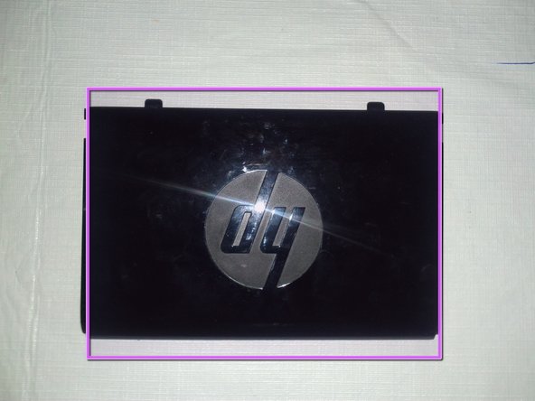
    • Make sure you have the kickstand out as if it was up right.

    • Lift up the kickstand with your hand.

  3. HP Touchsmart 300 Power Supply Replacement: étape 3, image 1 de 2 HP Touchsmart 300 Power Supply Replacement: étape 3, image 2 de 2
    • Remove the two screws with a flat head screwdriver.

    • Back panel screw compared to other sizes screws that will be removed later.

    • Step 14 has a note on all the screws removed in this guide.

  4. HP Touchsmart 300 Power Supply Replacement: étape 4, image 1 de 3 HP Touchsmart 300 Power Supply Replacement: étape 4, image 2 de 3 HP Touchsmart 300 Power Supply Replacement: étape 4, image 3 de 3
    • After the screws are removed, slide out off side panels.

    • Then left them up and remove them off to the side.

    • What the back side panels look like.

    • Remove both side panels.

  5. HP Touchsmart 300 Power Supply Replacement: étape 5, image 1 de 1
    • Back side panels should now be removed.

    • Memory Ram Sticks, SO-DIMM

    • SATA Hard Drive 3.5"

    • DVD/CD-rom Drive

  6. HP Touchsmart 300 Power Supply Replacement: étape 6, image 1 de 3 HP Touchsmart 300 Power Supply Replacement: étape 6, image 2 de 3 HP Touchsmart 300 Power Supply Replacement: étape 6, image 3 de 3
    • Next we'll be removing this panel.

    • Put your finger under the plastic panel and left up with your finger. The panel should put up a bit, then do the same thing on the other side.

    • Panel once removed.

  7. HP Touchsmart 300 Power Supply Replacement: étape 7, image 1 de 2 HP Touchsmart 300 Power Supply Replacement: étape 7, image 2 de 2
    • Now remove the last panel, just like you did with the last one. It should pop up with your figner and be removed.

    • Put one of your fingers under the plastic and pull up.

    • What the panel looks like once removed.

  8. HP Touchsmart 300 Power Supply Replacement: étape 8, image 1 de 3 HP Touchsmart 300 Power Supply Replacement: étape 8, image 2 de 3 HP Touchsmart 300 Power Supply Replacement: étape 8, image 3 de 3
    • Now remove the HB screws to remove the kickstand. Use a flat head screwdriver to remove the four screws.

    • Note: Slide the kickstand down so the hook in the metal gets released. This will let you left up and remove the kickstand.

    • What the kickstand looks like once removed.

  9. HP Touchsmart 300 Power Supply Replacement: étape 9, image 1 de 3 HP Touchsmart 300 Power Supply Replacement: étape 9, image 2 de 3 HP Touchsmart 300 Power Supply Replacement: étape 9, image 3 de 3
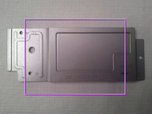
    • Now remove the three TC screws to remove the heatsink cover.

    • Note: I took the picture after I removed the three screws. Also side note, the TC screws are the same size at the CB screws removed later.

    • What heatsink cover looks like removed.

    • The back of the HP Touchsmart 300 after the heatsink cover was removed.

  10. HP Touchsmart 300 Power Supply Replacement: étape 10, image 1 de 2 HP Touchsmart 300 Power Supply Replacement: étape 10, image 2 de 2
    • Remove the nine screws labeled "CB" for the fans cover, with a flat head screwdriver. These are the 8 shown circled, plus 1 more in the central black area.

    • After the CB screws are removed, lift up the fans cover. It will be tethered by connecting wires to the motherboard. Some repairs can be done without untethering, just shifting the cover.

    • To remove the metal panel entirely (assumed below), you will have to unplug 2+ connectors from the motherboard. (More if you have a model with active external connectors like CATV, etc.) An alternative may be to detach the external-connector plate from the fans cover with the 3 screws label "IO-C", leaving just that small plate tethered.

    • I don't have a picture of this fans cover. Just be aware it is the biggest metal panel removed.

  11. HP Touchsmart 300 Power Supply Replacement: étape 11, image 1 de 1
    • When remove the CPU heatsink it's best to heat up the heatsink with a blow dryer so the thermal paste heats up. This way you don't rip the CPU out of the motherboard socket.

    • Remove the CPU heatsink screws.

    • Make sure you do the normal CPU unscrew method. For example, start with the upper left, unscrew just a bit, then go to the lower right and unscrew just a bit. Next jump to the lower left, unscrew just a bit, then next the upper right. Continue this until you can remove it.

    • If the heatsink doesn't easily left up, heat it up more with a blow dryer. To make sure you don't rip out the CPU. Ripping out the CPU from the motherboards socket could damage the CPU and the motherboard.

  12. HP Touchsmart 300 Power Supply Replacement: étape 12, image 1 de 1
    • CPU after removing the heatsink.

    • GPU after removing the heatsink, aka video card.

    • WiFi mini PCI card.

    • Fan for the CPU/GPU heatsink.

    • Power supply fan.

    • Now you can replace the CPU.

    • It's best to clean out both fans, if your having overheating issues. Or to prevent it from happening in the future.

  13. HP Touchsmart 300 Power Supply Replacement: étape 13, image 1 de 2 HP Touchsmart 300 Power Supply Replacement: étape 13, image 2 de 2
    • This part is about cleaning.

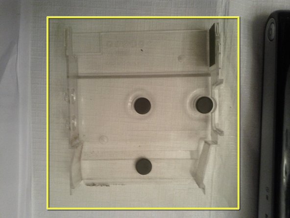
    • There is a plastic tray just below the heatsink fan. This can be removed and cleaned if there is a lot of dust in it.

    • Plastic tray once removed.

  14. HP Touchsmart 300 Power Supply Replacement: étape 14, image 1 de 1
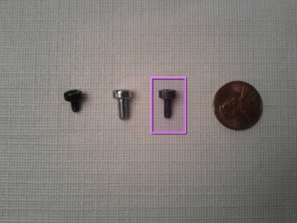
    • Types of screws that have been removed. This is to help when putting back together everything.

    • TC and CB screws. For the heatsink cover and fans cover metal panels. 11 total

    • HB screws. For the kickstand. 4 total

    • Screws for the side panels. 2 total

    • The penny is to help with scale.

    • Follow Ashton's iFixIt instructions through his Step 10. Then we need to remove parts of the plastic frame, detailed next. Instructions that follow assume that the unit is screen-down with the lower edge and feet facing you.

  15. HP Touchsmart 300 Power Supply Replacement: étape 16, image 1 de 1
    • Remove the left and right rear trim. To do this, view the plastic frame and find the small rectangular slots outward of each foot and adjoining a seam. Insert a flathead screwdriver and pull gently towards you to unhook each trim piece, then complete removal by hand. [ 2 photos]

    • Remove the feet. Also unplug the USB flash drive near the right foot.

    • Underneath where the side trim was, remove the 6 silver-colored screws indicated. It is not necessary to remove the black screws.

    • Removal of the rear plastic frame can now be done. Start at the lower “foot” edge, and press gently along the length of the mating, perforated plastic front frame, while pulling gently upward on the rear frame. There are 3 hooks along the length of the lower edge to detach by this process. Then angle it up and remove the top edge last.

    • The power supply is now exposed at the lower center, but additional items must be cleared away.

    • Begin with the disk drive enclosure to its left, which has a wire bale handle. Unscrew the single spring-mounted captive screw (indicated by a screwdriver symbol), and pull up the handle. Prop the drive at an angle (e.g., with a screwdriver handle). It is not necessary to remove the drive.

    • Remove the 3 screws holding the smaller fan unit that abuts the power supply, and remove it and the plastic duct shim.

    • Gently unplug the P2 connector (not shown) between this fan and power supply.

    • Remove 3 screws (2 marked “PS-U”) holding the power supply in place. A fourth screw, nearest the frame edge, is not necessary to remove; it secures the power supply cradle.

    • The power supply is mechanically loose. To finish removal, first detach connector P1 from the motherboard as shown (pry at alternating ends of seam with thin screwdriver while initially pressing the part of black central latch closest to you).

    • Also detach white connector P3, that runs under the fan (and note clip) to the circuit board protruding from under the DVD drive cage. Again, a thin screwdriver can help.

Conclusion

When reversing these steps to install a new power supply, first arrange the power supply’s cables in the channel beneath the supply so that the supply sits snugly. Reinstall the 3 screws. Only then attach P1, P2, and P3. Before remounting the fan, route the P3 cable under its clip.

3 autres ont terminé cette réparation.

Glenn P

Membre depuis le 09/29/12

227 Réputation

1 tutoriel rédigé

0 commentaires

Ajouter un commentaire

Nombre de vues :

Dernières 24 heures : 0

7 derniers jours : 0

30 derniers jours : 0

Total : 2,987