Cette version peut contenir des modifications incorrectes. Passez au dernier aperçu vérifié.
Ce dont vous avez besoin
-
Cette étape n’est pas traduite. Aidez à la traduire
-
To begin the disassembly of the device, place it on a flat surface with the screen facing down.
-
-
Cette étape n’est pas traduite. Aidez à la traduire
-
Remove the four screws found on the back cover of the device.
-
-
Cette étape n’est pas traduite. Aidez à la traduire
-
Carefully remove the back cover using the spudger against the grooves along the sides of the iPAQ.
-
-
Cette étape n’est pas traduite. Aidez à la traduire
-
At this point, a yellow ribbon will be connecting both the front and back panels of the device. Carefully use the plastic opening tool to detach the ribbon from the connector pins.
-
-
Cette étape n’est pas traduite. Aidez à la traduire
-
Remove SD card on top of device by pushing and then releasing.
-
-
-
Cette étape n’est pas traduite. Aidez à la traduire
-
Remove the ribbon cable connected to display logic board by pulling the plastic clips on both sides towards top of device.
-
Use plastic opening tool to carefully pull brown ribbon cable from connector.
-
-
Cette étape n’est pas traduite. Aidez à la traduire
-
Use the plastic opening tool to carefully remove the display logic board from its housing.
-
Unplug connector from the opposite end of the display logic board.
-
Completely remove component.
-
-
Cette étape n’est pas traduite. Aidez à la traduire
-
Flip up black plastic clip on large ribbon cable connector located towards center of mother board.
-
Use plastic opening tool to carefully remove ribbon cable from connector.
-
-
Cette étape n’est pas traduite. Aidez à la traduire
-
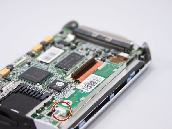
Locate clear/grey ribbon cable in bottom corner of device.
-
Gently pry cable out of connector with plastic opening tool.
-
Use hands or tweezers to remove if necessary.
-
-
Cette étape n’est pas traduite. Aidez à la traduire
-
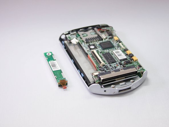
Remove three small screws from each corner of the motherboard using phillips head screwdriver.
-
Use your hands/plastic opening tool to carefully lift the mother board out of housing.
-
Place the motherboard to the side.
-
-
Cette étape n’est pas traduite. Aidez à la traduire
-
Locate the four blue plastic clips surrounding the square screen housing.
-
Pry back clips with your hands.
-
Use the plastic opening tool to remove the entire screen assembly from the housing.
-


Annulation : je n'ai pas terminé ce tutoriel.
Une autre personne a terminé cette réparation.
Équipe

Eastern Washington University, Team 1-3, Plummer Spring 2015 Membre de l'équipe Eastern Washington University, Team 1-3, Plummer Spring 2015
EWU-PLUMMER-S15S1G3
4 membres
5 tutoriels rédigés