Aller au contenu principal

Hamilton Beach 49980A Power Cord Replacement

Ce dont vous avez besoin

  1. Hamilton Beach 49980A Power Cord Replacement, Bottom Plate: étape 1, image 1 de 3 Hamilton Beach 49980A Power Cord Replacement, Bottom Plate: étape 1, image 2 de 3 Hamilton Beach 49980A Power Cord Replacement, Bottom Plate: étape 1, image 3 de 3
    • Begin by inverting the coffee maker and resting it on a flat surface to make working on the bottom easier.

    • Now use a Y0 bit to remove all of the .46 inch long screws from the bottom.

    • Lift the plate to remove it from the rest of the machine.

  2. Hamilton Beach 49980A Power Cord Replacement, Motherboard: étape 2, image 1 de 1
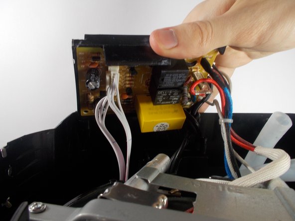
    • Once the bottom plate is removed, use a PH1 bit to remove the .525 inch long screws holding the motherboard bracket in the main housing.

  3. Hamilton Beach 49980A Power Cord Replacement: étape 3, image 1 de 2 Hamilton Beach 49980A Power Cord Replacement: étape 3, image 2 de 2
    • Using a PH1 bit, remove the two .425 inch long screws holding down the white power cord bracket. This will give you the slack in the wire that you need to work on the motherboard.

    • Carefully remove the large white connector that has multiple wires attached to it. This is the wire connected to the button functions on the interface of the coffee maker.

  4. Hamilton Beach 49980A Power Cord Replacement, Power Cord: étape 4, image 1 de 1
    • After removing the motherboard, follow the powercord down to where it splits. It will be connected to the motherboard in two places with solder. Locate these two points.

  5. Hamilton Beach 49980A Power Cord Replacement: étape 5, image 1 de 1
    • Using a soldering iron, heat up one soldered point that is holding the power cord in place. While the solder is hot, carefully pull the cord out of the connection.

    • The wire will be hot. You may want to use pliers to remove it.

  6. Hamilton Beach 49980A Power Cord Replacement: étape 6, image 1 de 1
    • Locate the second half of the power cord. On the underside of the motherboard, heat up the soldered connection and remove the wire while the solder is hot.

    • When replacing any soldered components, you may want to apply new solder.

Conclusion

To reassemble your device, follow these instructions in reverse order.

Paul Shipley

Membre depuis le 03/25/16

201 Réputation

2 tutoriels rédigés

Équipe

UMass Dartmouth, Team 1-7, Miles Spring 2016 Membre de l'équipe UMass Dartmouth, Team 1-7, Miles Spring 2016

UMASSD-MILES-S16S1G7

3 membres

7 tutoriels rédigés

0 commentaires

Ajouter un commentaire

Nombre de vues :

Dernières 24 heures : 0

7 derniers jours : 0

30 derniers jours : 3

Total : 476