Cette version peut contenir des modifications incorrectes. Passez au dernier aperçu vérifié.
Ce dont vous avez besoin
-
Cette étape n’est pas traduite. Aidez à la traduire
-
Remove the four 1/8-inch black machine screws using a Phillips #00 screwdriver.
-
-
Cette étape n’est pas traduite. Aidez à la traduire
-
Remove three steel-finish, pan-head, 1/64 x 3/16" machine screws identified in the photograph, using the Phillips #0 screwdriver.
-
-
Cette étape n’est pas traduite. Aidez à la traduire
-
Using your fingers and/or a metal spudger, gently release the plastic locking tabs of the front panel assembly from the steel enclosure while prying the front panel assembly away from the steel enclosure with your fingers.
-
-
-
Cette étape n’est pas traduite. Aidez à la traduire
-
Gently remove the front panel from the steel enclosure.
-
-
Cette étape n’est pas traduite. Aidez à la traduire
-
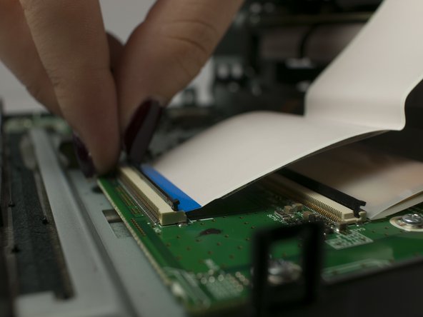
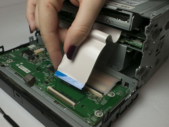
Gently separate the ribbon cable from from ZIF connector on the circuit board using a metal smudger.
-
-
Cette étape n’est pas traduite. Aidez à la traduire
-
Remove seven 1/64 x 3/16" screws from the top panel using the Phillips #0 screwdriver.
-
Remove the top panel.
-
-
Cette étape n’est pas traduite. Aidez à la traduire
-
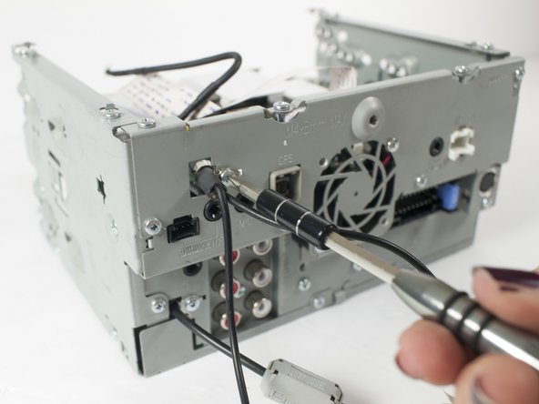
Disconnect Video Out/Rear View Camera cable from circuit board.
-
Remove the Video Out/Rear View Camera cable retaining clip using after removing 0-64 x 3/16" machine screw using a Phillips #0 screwdriver.
-
Withdraw Video Out/Rear View Camera cable from rear panel.
-
-
Cette étape n’est pas traduite. Aidez à la traduire
-
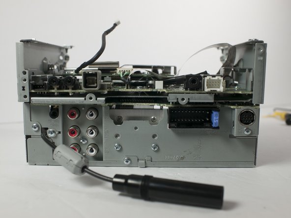
Remove the five 1/64 x 3/16" machine screws from the rear panel identified in the photograph.
-
Remove rear panel.
-
-
Cette étape n’est pas traduite. Aidez à la traduire
-
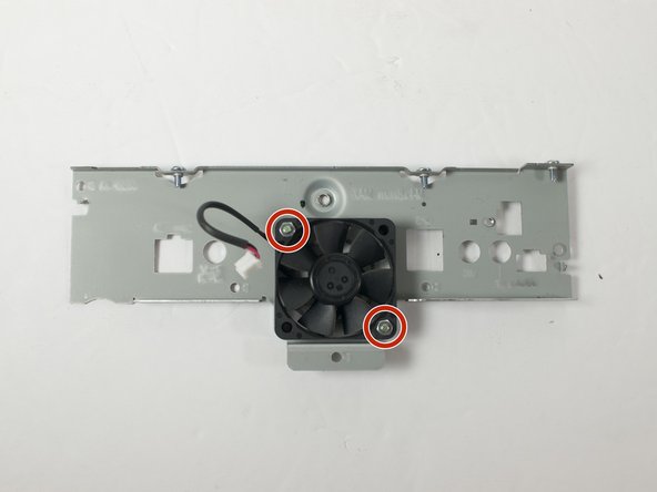
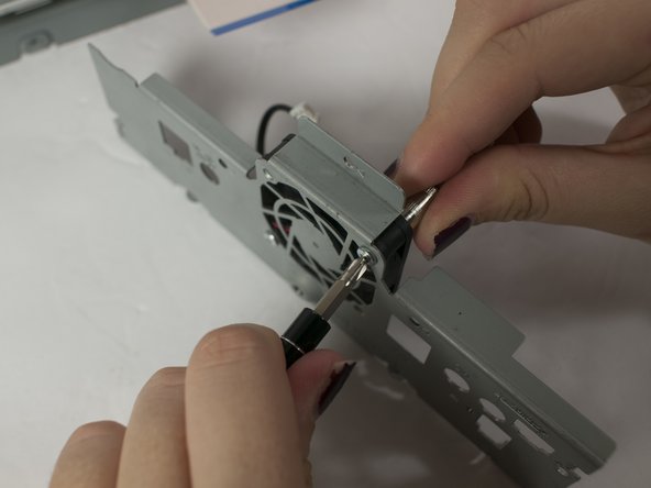
Remove the two 1-64 x 1/2" machine screws and the retaining nuts that fasten the cooling fan to the rear panel using the Phillips #0 screwdriver and the 5/32" socket.
-


Équipe

Linn Benton Community College, Team S1-G6, Johnson Fall 2018 Membre de l'équipe Linn Benton Community College, Team S1-G6, Johnson Fall 2018
LBCC-JOHNSON-F18S1G6
3 membres
8 tutoriels rédigés