Cette version peut contenir des modifications incorrectes. Passez au dernier aperçu vérifié.
Ce dont vous avez besoin
-
Cette étape n’est pas traduite. Aidez à la traduire
-
Unscrew the four 3.5mm side screws with a Phillips #1 screwdriver.
-
-
Cette étape n’est pas traduite. Aidez à la traduire
-
Use a spudger to unhook the plastic clips on the sides and top of the front panel. There are two clips on each side and one clip on the top.
-
-
Cette étape n’est pas traduite. Aidez à la traduire
-
Pull the top of the front panel out and down to remove front panel.
-
-
Cette étape n’est pas traduite. Aidez à la traduire
-
Unscrew the three 5mm screws from the top of the device using a Phillips #1 screwdriver.
-
Lift up to remove the top casing.
-
-
Cette étape n’est pas traduite. Aidez à la traduire
-
Flip up the black clasp with a spudger to disconnect the large white ribbon cable connecting the CD drive to the board underneath.
-
-
Cette étape n’est pas traduite. Aidez à la traduire
-
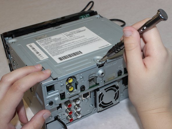
Carefully unplug the fan power cord with the tweezers.
-
-
-
Cette étape n’est pas traduite. Aidez à la traduire
-
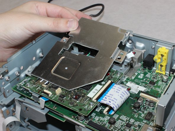
Unscrew the three 5mm length screws with the Phillips #1 screwdriver.
-
Remove the metal plate
-
-
Cette étape n’est pas traduite. Aidez à la traduire
-
Unscrew the three 5.5mm long screws with a Phillips #1 screwdriver.
-
-
Cette étape n’est pas traduite. Aidez à la traduire
-
Remove the four 5.5mm screws with the Phillips #1 screwdriver.
-
-
Cette étape n’est pas traduite. Aidez à la traduire
-
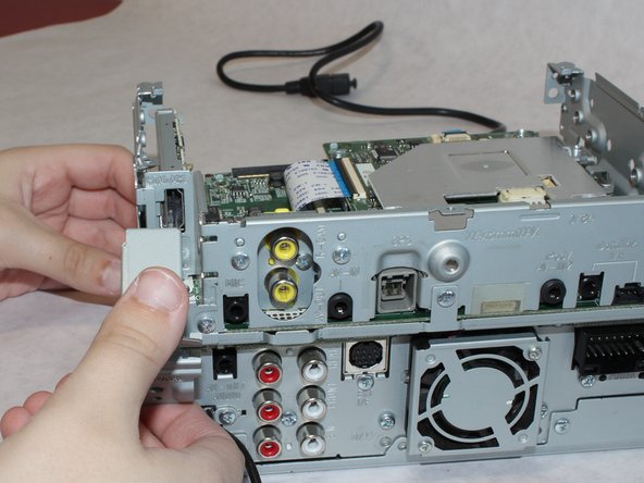
Lift the top part of the unit up from the lower chassis.
-
-
Cette étape n’est pas traduite. Aidez à la traduire
-
Remove the two 13mm long screws with a Phillips #1 screwdriver.
-
-
Cette étape n’est pas traduite. Aidez à la traduire
-
Using a spudger, undo the clasp to disconnect the large white ribbon cable.
-
-
Cette étape n’est pas traduite. Aidez à la traduire
-
Remove the 5mm screw with teeth from the casing with a Phillips #1 screwdriver.
-
-
Cette étape n’est pas traduite. Aidez à la traduire
-
Remove the four 5mm screws with a Phillips #1 screwdriver.
-
-
Cette étape n’est pas traduite. Aidez à la traduire
-
Remove the 5.5mm screw from the HDMI cable cover using a Phillips #2 screwdriver.
-
-
Cette étape n’est pas traduite. Aidez à la traduire
-
Remove the 5mm screw with a Phillips #1 screwdriver.
-
-
Cette étape n’est pas traduite. Aidez à la traduire
-
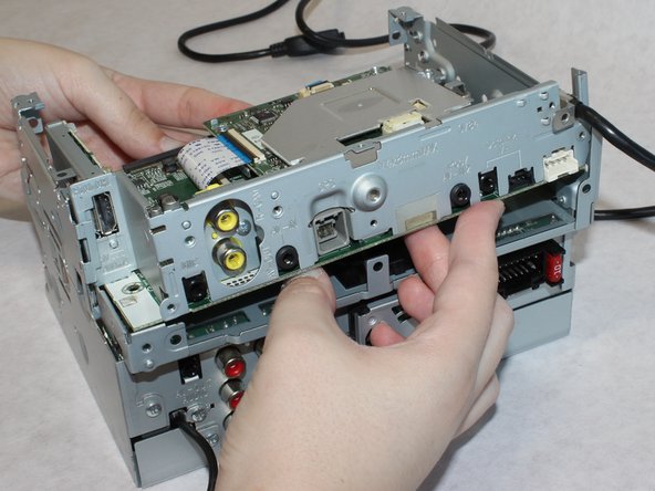
Remove the two 5.5mm screws from the back.
-
Lift the upper portion of the stereo free from the chassis.
-
-
Cette étape n’est pas traduite. Aidez à la traduire
-
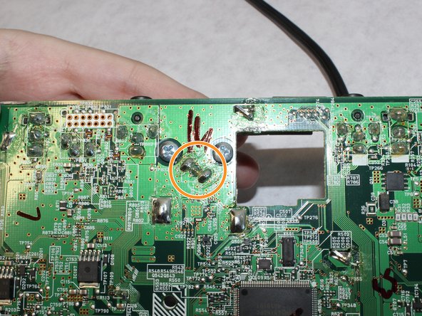
Remove the two screws underneath the GPS connector.
-
Desolder the GPS connector.
-
-
Cette étape n’est pas traduite. Aidez à la traduire
-
To remove and reinsert the connector, on the top side of the board, use your finger to gently lift the metal plate to get enough clearance.
-


Annulation : je n'ai pas terminé ce tutoriel.
Une autre personne a terminé cette réparation.
Équipe

Washington State, Team S1-G1, Hope Fall 2018 Membre de l'équipe Washington State, Team S1-G1, Hope Fall 2018
WSU-HOPE-F18S1G1
4 membres
6 tutoriels rédigés