Cette version peut contenir des modifications incorrectes. Passez au dernier aperçu vérifié.
Ce dont vous avez besoin
-
Cette étape n’est pas traduite. Aidez à la traduire
-
Lift the cold water reserve lid up to reveal its hinge.
-
Using either the metal spudger or the opening tool, gently pry the plastic out of the metal axle.
-
-
Cette étape n’est pas traduite. Aidez à la traduire
-
Repeat the last step on the other hinge, making sure to keep a firm grasp on the lid as it comes off to avoid dropping it.
-
-
Cette étape n’est pas traduite. Aidez à la traduire
-
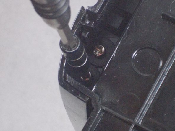
Remove two 9 mm Phillips #1 screws.
-
The screws are located on the top of where the K-Cup would be.
-
-
Cette étape n’est pas traduite. Aidez à la traduire
-
Once you remove the screws, the top cover should come out.
-
You will then want to remove these screws which are the same size.
-
-
Cette étape n’est pas traduite. Aidez à la traduire
-
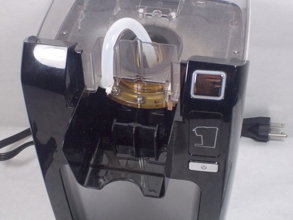
Once you get those removed, you are going to want to pull on the hose until it pops off.
-
Once the hose comes off, the needle will fall out by itself.
-
-
Cette étape n’est pas traduite. Aidez à la traduire
-
Remove two 14 mm Phillips #2 screws.
-
Remove two 12 mm Phillips #2 screws.
-
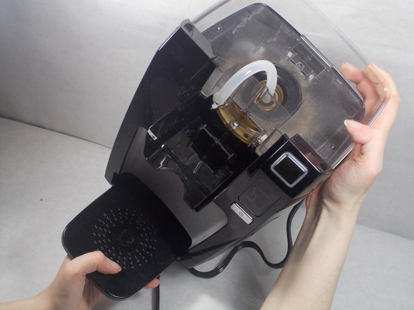
Lift the arm off the assembly. This will reveal the tank hole as shown.
-
-
Cette étape n’est pas traduite. Aidez à la traduire
-
Remove two 9.7 mm Phillips #2 screws.
-
Remove two 11.5 mm Phillips #2 screws.
-
Remove the cold water reserve arm's plug from the arm itself in order to allow access to the base screws.
-
-
-
Cette étape n’est pas traduite. Aidez à la traduire
-
Remove two 18 mm Phillips #2 screws.
-
Finally, detach the arm from the cold water reserve basin.
-
-
Cette étape n’est pas traduite. Aidez à la traduire
-
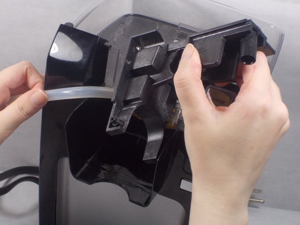
Pull the head assembly forward to reveal the two plastic axle points that keep the head assembly attached to the base.
-
-
Cette étape n’est pas traduite. Aidez à la traduire
-
Using the iFixit Opening Tool, gently pry apart the plastic head assembly piece from both the body's axles and its left to remove it.
-
-
Cette étape n’est pas traduite. Aidez à la traduire
-
Remove two 14 mm Phillips #2 screws.
-
Remove two 12 mm Phillips #2 screws.
-
-
Cette étape n’est pas traduite. Aidez à la traduire
-
Flip over the device.
-
Remove four 11.5 mm Phillips #2 screws.
-
-
Cette étape n’est pas traduite. Aidez à la traduire
-
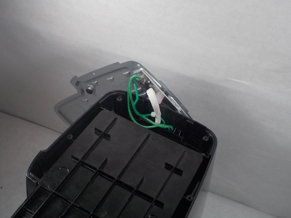
Reposition the metal lid while keeping the heat sink attached in order to reach the screws underneath.
-
-
Cette étape n’est pas traduite. Aidez à la traduire
-
Begin to pry open the front plate using the iFixit Opening Tool as shown.
-
Pry upwards in order to take the cover off.
-
-
Cette étape n’est pas traduite. Aidez à la traduire
-
Remove the button housing to access the buttons.
-
The brew buttons can be easily popped out of place by pushing inwards from the front of the unit.
-


Équipe

UMass Dartmouth, Team S5-G7, Gulbrandsen Fall 2018 Membre de l'équipe UMass Dartmouth, Team S5-G7, Gulbrandsen Fall 2018
UMASSD-GULBRANDSEN-F18S5G7
3 membres
5 tutoriels rédigés