Introduction
Follow this guide to replace the power components on a 2014 Kushlan cement mixer model 600DDS.
This guide is for replacing the capacitor, on/off switch, and power cord simultaneously. If only one of these components needs to be replaced, follow the respective individual guide.
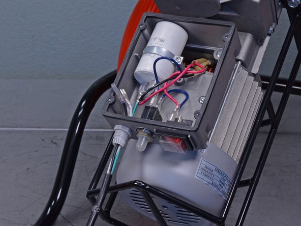
To prevent electric shock, leave the device unplugged for 20 minutes to allow the capacitor to discharge before you begin.
Ce dont vous avez besoin
-
-
Use a 13 mm socket to remove the two bolts securing the motor cover to the frame.
-
-
-
Use a Phillips screwdriver to remove the four screws securing the electrical panel.
-
-
-
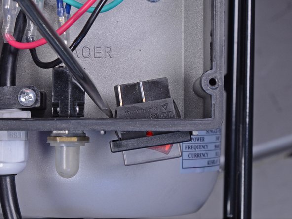
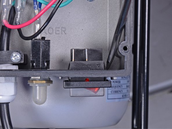
Use a pair of needle-nose pliers to disconnect the four wires from the back of the on/off switch.
-
-
-
-
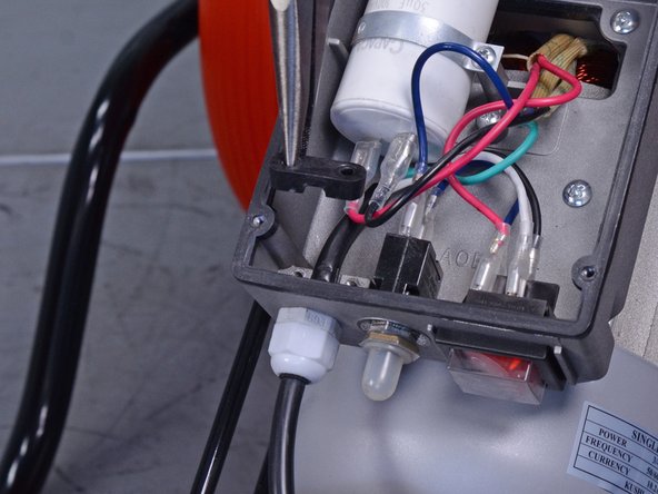
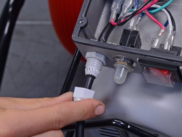
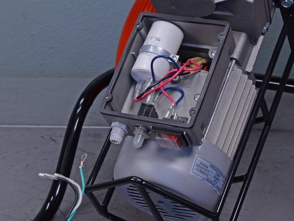
Use a Phillips screwdriver to remove the two screws securing the fastener behind the strain relief fitting.
-
-
-
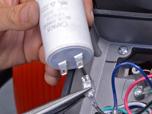
Use a Phillips screwdriver to remove the screw securing the capacitor support.
-


To reassemble your device, follow these instructions in reverse order.
To reassemble your device, follow these instructions in reverse order.
Annulation : je n'ai pas terminé ce tutoriel.
6 autres ont terminé cette réparation.

Un commentaire
Very well presented. The photos were very sharp and clear. From looking at your photos it would apear that you can reverse the motor rotation by reversing the 2 capacitor leads. This would make empting the mixer eaiser in some situations. Do you agree?
Thank you,
Drew Watson