Aller au contenu principal

Lavazza A Modo Mio Minù PCB & Power Switch Removal

Ce dont vous avez besoin

  1. Lavazza A Modo Mio Minù PCB & Power Switch Removal, Remove the Brew Switch: étape 1, image 1 de 2 Lavazza A Modo Mio Minù PCB & Power Switch Removal, Remove the Brew Switch: étape 1, image 2 de 2
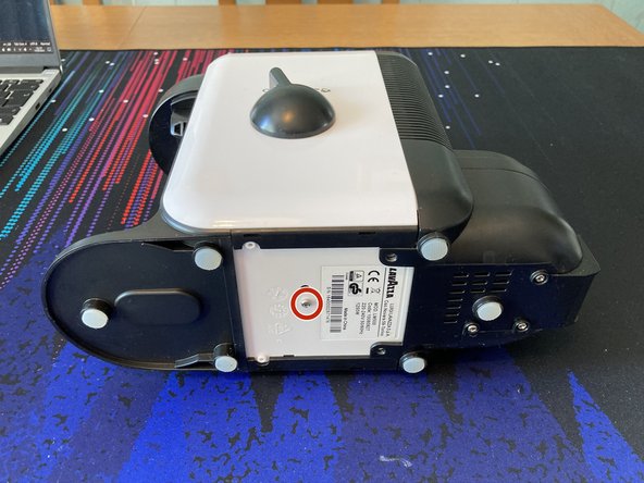
    • Start by removing the water container, capsule basket and both drip trays.

    • The switch simply pulls off. Hold the lever and use a spudger on the opposite side to ease it off its stem.

    • The machine is likely to still contain some water - it's recommended to mop up the residual before continuing:

    • In the water filter, below the water container.

    • Around the capsule basket.

    • Around and above the clear plastic drip tray (rear-most).

  2. Lavazza A Modo Mio Minù PCB & Power Switch Removal, Open the Mains Wiring Panel: étape 2, image 1 de 3 Lavazza A Modo Mio Minù PCB & Power Switch Removal, Open the Mains Wiring Panel: étape 2, image 2 de 3 Lavazza A Modo Mio Minù PCB & Power Switch Removal, Open the Mains Wiring Panel: étape 2, image 3 de 3
    • This will expose Mains wiring! The machine Must be un-plugged before this step.

    • Remove 3x P2 M3x14mm self-tapping screws.

    • Slide the panel cover off.

  3. Lavazza A Modo Mio Minù PCB & Power Switch Removal, Disconnect C13 Kettle Socket: étape 3, image 1 de 1
    • Use a 3mm Flathead screwdriver to un-screw 3x wire-traps connecting the Live, Neutral and Earth wires to the rest of the machine. Pull the wires free.

  4. Lavazza A Modo Mio Minù PCB & Power Switch Removal, Disconnect Water Filter: étape 4, image 1 de 1
    • Remove 2x P2 M3x12mm self-tapping screws.

    • The right-hand screw is hard to access, but a straight shaft can just about get the right angle to unscrew & tighten it from the user-side of the water tubes.

    • Do not be tempted to break off the plastic guard for better access! This is a backup guard to prevent water from leaking onto the mains wiring below it.

    • There is a silicone gasket sandwiched between the water filter and the top of the rear housing (beneath where the water container sits). When re-assembling, remember to place the gasket back on the water filter housing before screwing it back into place.

  5. Lavazza A Modo Mio Minù PCB & Power Switch Removal, Rear Housing Removal Preparation: étape 5, image 1 de 2 Lavazza A Modo Mio Minù PCB & Power Switch Removal, Rear Housing Removal Preparation: étape 5, image 2 de 2
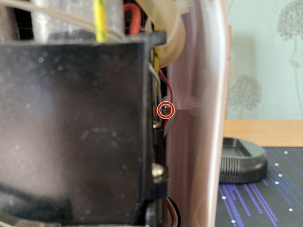
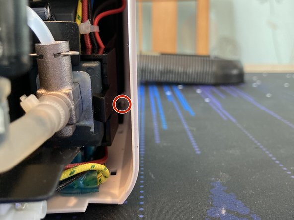
    • Remove 1x P2 M3x14mm self-tapping screw.

    • The two black accent strips do not require removal for this guide, but can be gently pried off using a pry tool.

  6. Lavazza A Modo Mio Minù PCB & Power Switch Removal, Rear Housing Removal: étape 6, image 1 de 2 Lavazza A Modo Mio Minù PCB & Power Switch Removal, Rear Housing Removal: étape 6, image 2 de 2
    Outil utilisé dans cette étape :
    Tweezers
    $4.99
    J'achète
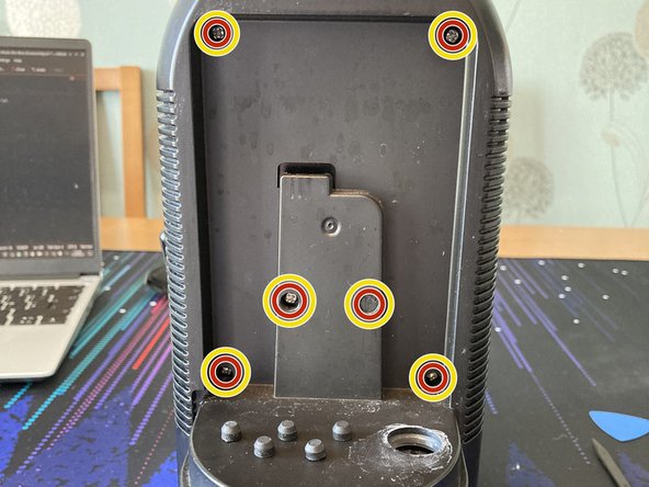
    • Use a spudger, pair of tweezers, small screwdriver bit, your fingers or a deal with the devil to remove 6x rubber plugs.

    • One of these was much harder than the others and required carving out some of the rubber to get a tool down its side.

    • Remove the 6x P2 M3x14mm self-tapping screws hidden behind these plugs.

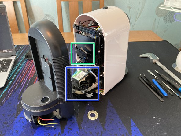
    • Separate the rear housing from the rest of the machine. Be careful not to lose the water filter's gasket.

    • Shown here is the microswitch that detects whether the water container is installed.

    • This is the pump that brings water from the water container up to the water heater.

  7. Lavazza A Modo Mio Minù PCB & Power Switch Removal, Remove Braces: étape 7, image 1 de 1
    • This step is technically optional, but will provide more access for the tight-space work to follow.

    • Remove 4x P2 M3x14mm self-tapping screws.

    • Note the orientations of the braces for re-assembly.

    • Pull the braces off their posts to remove them.

  8. Lavazza A Modo Mio Minù PCB & Power Switch Removal, Remove Main Housing - Groundwork: étape 8, image 1 de 3 Lavazza A Modo Mio Minù PCB & Power Switch Removal, Remove Main Housing - Groundwork: étape 8, image 2 de 3 Lavazza A Modo Mio Minù PCB & Power Switch Removal, Remove Main Housing - Groundwork: étape 8, image 3 de 3
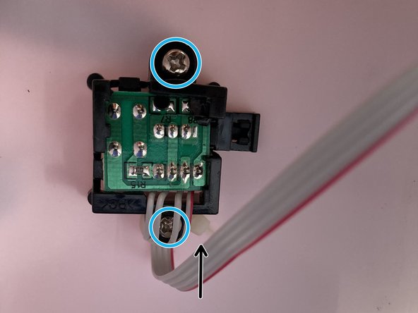
    • Use a spudger and/or your fingers to disconnect the 4-way JST connector from the PCB.

    • Carefully take up the slack of the ribbon cable by pulling gently on the exposed part of the cable near the power button.

    • The cable will Not pull all the way through, due to it being routed through a channel that is smaller than the JST connector housing. Stop pulling when you feel resistance.

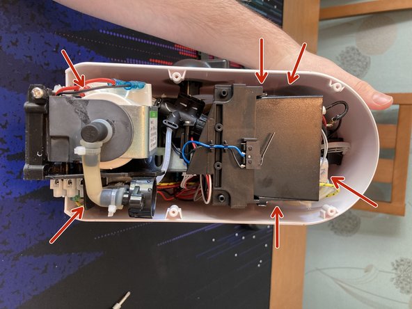
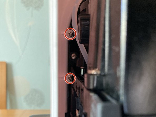
    • Remove 6x P2 M3x14mm self-tapping screws, located inside the housing, at the front of the unit (furthest from the opening).

    • The internal locations of these screws are shown in the next two steps.

    • Using a magnetic 6-inch rigid-shaft screwdriver would make this much easier, but it is also possible to use the iFixIt Mako Driver Kit's flexible extension adapter instead.

  9. Lavazza A Modo Mio Minù PCB & Power Switch Removal, Remove Main Housing - Screw Close-Ups 1: étape 9, image 1 de 3 Lavazza A Modo Mio Minù PCB & Power Switch Removal, Remove Main Housing - Screw Close-Ups 1: étape 9, image 2 de 3 Lavazza A Modo Mio Minù PCB & Power Switch Removal, Remove Main Housing - Screw Close-Ups 1: étape 9, image 3 de 3
    • The first 3x P2 M3x14mm self-tapping screws.

  10. Lavazza A Modo Mio Minù PCB & Power Switch Removal, Remove Main Housing - Screw Close-Ups 2: étape 10, image 1 de 2 Lavazza A Modo Mio Minù PCB & Power Switch Removal, Remove Main Housing - Screw Close-Ups 2: étape 10, image 2 de 2
    • The last 3x P2 M3x14mm self-tapping screws.

  11. Lavazza A Modo Mio Minù PCB & Power Switch Removal, Remove Main Housing - Finale: étape 11, image 1 de 3 Lavazza A Modo Mio Minù PCB & Power Switch Removal, Remove Main Housing - Finale: étape 11, image 2 de 3 Lavazza A Modo Mio Minù PCB & Power Switch Removal, Remove Main Housing - Finale: étape 11, image 3 de 3
    • Be careful not to put strain on the ribbon cable! Ensure you have pulled through some slack near the power button to facilitate removal of the main housing.

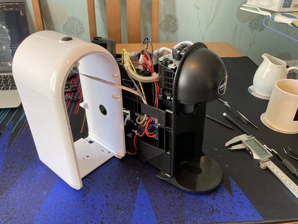
    • Slowly pull the main housing free from the rest of the machine, taking care to move & flex obstructions out of the way.

    • Carefully angle the housing to the machine's Left side (in these pictures, towards the technician) and bring the housing next to the machine to slacken off the ribbon cable.

    • Shown here is the water heater.

    • This is likely to contain a second pump that pushes the heated water through the brew capsule at a higher pressure.

  12. Lavazza A Modo Mio Minù PCB & Power Switch Removal, Free the Power Button Holder: étape 12, image 1 de 2 Lavazza A Modo Mio Minù PCB & Power Switch Removal, Free the Power Button Holder: étape 12, image 2 de 2
    • Taking care with the ribbon cable, remove 2x 12mm P2 self-tapping screws.

    • The ribbon cable exits the power button assembly towards the rear of the machine and then exits the main housing towards the front.

    • For re-assembly, there is a cable tie that provides strain relief by the rear-most screw. Ensure this is hooked over the rear-most plastic post in the main housing when re-assembling (this is the post that the rear-most screw screws into).

  13. Lavazza A Modo Mio Minù PCB & Power Switch Removal, Free the Power Button PCB: étape 13, image 1 de 3 Lavazza A Modo Mio Minù PCB & Power Switch Removal, Free the Power Button PCB: étape 13, image 2 de 3 Lavazza A Modo Mio Minù PCB & Power Switch Removal, Free the Power Button PCB: étape 13, image 3 de 3
    • Do not attempt to remove the the JST connector shown here. It is one single piece, with the wires crimped and inserted directly into the housing that is soldered to the PCB. It is very difficult to remove the ribbon cable from the PCB without damaging the pin crimps.

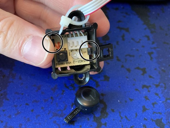
    • Use a pair of sturdy tweezers or your fingers to un-clip the power button facade from the power button PCB holder.

    • Carefully flex the PCB clips and move the PCB past them in order to clear the housing. The PCB can then be passed back through the housing at an angle, to finish separation.

    • These clips seem to be stiff & brittle and I broke one of the clips while attempting this. Once re-assembled, the power button assembly should hold the PCB in place.

    • For added peace of mind, a sufficiently small amount of cyanoacrylate (superglue) could be used during reassembly to secure the PCB in place. The glue joint could then be easily cracked during future disassembly to free the PCB.

  14. Lavazza A Modo Mio Minù PCB & Power Switch Removal, Disconnect the Core PCB: étape 14, image 1 de 3 Lavazza A Modo Mio Minù PCB & Power Switch Removal, Disconnect the Core PCB: étape 14, image 2 de 3 Lavazza A Modo Mio Minù PCB & Power Switch Removal, Disconnect the Core PCB: étape 14, image 3 de 3
    • As a precaution, once the pins of the larger connectors are exposed, use a metal tool with high-voltage rated insulating handles to bridge the pins and short out any residual charge left in any capacitors.

    • This is due to the PCB containing "power supply components". This power supply should not pose a threat, but higher power devices (like those in PC PSUs) can store enough charge to cause elctrocution.

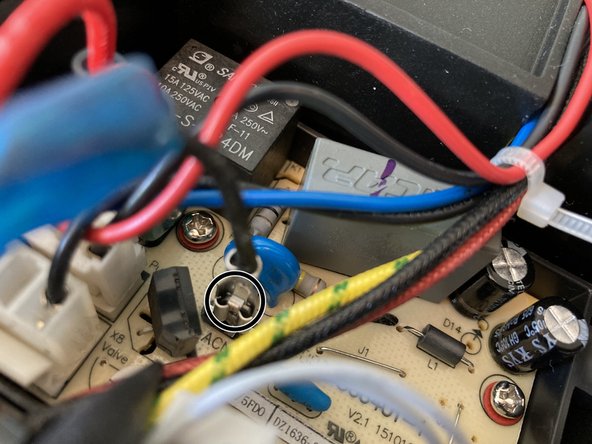
    • Disconnect 5 wire-to-board connectors.

    • Disconnect 3 crimped wire lugs. These lugs have a retaining clip under the plastic sheath. Either:

    • Press the lever through the plastic with tweezers while pulling on the lug.

    • Lift the plastic sheath off the lug and move it along the wire to expose each clip's lever. Press the lever with your fingers or tweezers and pull the lug off the PCB.

  15. Lavazza A Modo Mio Minù PCB & Power Switch Removal, Remove the Core PCB: étape 15, image 1 de 3 Lavazza A Modo Mio Minù PCB & Power Switch Removal, Remove the Core PCB: étape 15, image 2 de 3 Lavazza A Modo Mio Minù PCB & Power Switch Removal, Remove the Core PCB: étape 15, image 3 de 3
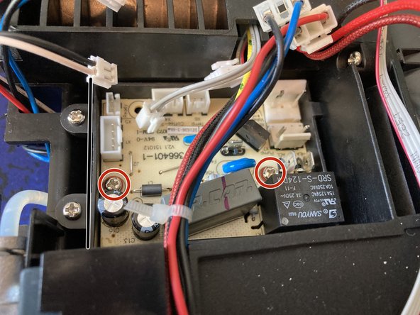
    • Remove 2x P2 M3x14mm self-tapping screws and accompanying washers.

    • Lift out the PCB, starting with the left edge and sliding out underneath the cable harness to the left-hand-side.

    • Pictured is the front and back of the PCB. Some of the higher-voltage (including Mains) carrying traces can be identified by the routed airgaps near some of the thicker traces. Other thick traces without these gaps may carry higher current at lower voltages (though this is Not a guarantee!).

    • The large black cube device on the front is a power relay capable of switching 250V 7A AC. This will be what modulates power to the water heater and thus controls the water temperature.

    • The largest package on the rear is a microcontroller and is likely to be what co-ordinates the operation of the machine. It would operate on inputs from the Power and Brew switches, temperature probes within the water heater, the microswitch for the water container and probably a water flow or pressure detector.

    • It would then directly drive the water pump and above-noted relay to control the coffee machine's operation; as well as the various LEDs dotted around the machine.

Conclusion

That's as far as I got! Further disassembly would require removal of the water pipes, which I didn't want to do.

To reassemble the machine, follow these instructions in reverse order.

Blair Edwards

Membre depuis le 09/17/22

241 Réputation

1 tutoriel rédigé

0 commentaires

Ajouter un commentaire

Nombre de vues :

Dernières 24 heures : 0

7 derniers jours : 12

30 derniers jours : 52

Total : 626