Aller au contenu principal

Lorex MC6950 Circuit Board Replacement

Ce dont vous avez besoin

  1. Lorex MC6950 Circuit Board Replacement, Circuit Board: étape 1, image 1 de 2 Lorex MC6950 Circuit Board Replacement, Circuit Board: étape 1, image 2 de 2
    • To remove the circuit board, you must begin by removing the three screw caps and the 15mm JIS 0 screws associated with them located on the plastic containment shell that the camera is in.

  2. Lorex MC6950 Circuit Board Replacement: étape 2, image 1 de 2 Lorex MC6950 Circuit Board Replacement: étape 2, image 2 de 2
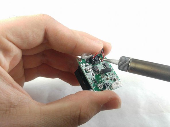
    • Next, the camera must be removed. A metal spudger will be useful to pry this out as it is sealed inside the outer containment shell.

    • Once the camera is removed, remove the wires from the outer containment shell.

    • Be careful. The metal spudger could damage the camera if not handled with care.

  3. Lorex MC6950 Circuit Board Replacement: étape 3, image 1 de 2 Lorex MC6950 Circuit Board Replacement: étape 3, image 2 de 2
    • With the camera in hand, the circuit board must be separated from the LED containment shell. There is a 5mm JIS 0 screw at every corner of the circuit board.

    • The wires attaching the circuit board to the shell should be removed as well.

  4. Lorex MC6950 Circuit Board Replacement: étape 4, image 1 de 2 Lorex MC6950 Circuit Board Replacement: étape 4, image 2 de 2
    • Now the motor, lens, and wires must be removed from the circuit board. There are three 5mm JIS 0 screws located on the lens side of the circuit board to remove the motor housing.

    • The motor housing will need to be soldered back onto the new circuit board when reassembling. The wires should come from the circuit board and connect to the motor housing on the opposite of the lens side of the circuit board.

  5. Lorex MC6950 Circuit Board Replacement: étape 5, image 1 de 1
    • The lens has two 5 mm JIS 0 screws located under the motor's previous location.

    • As a final step, the wires that connected the board to the containment shell will need to be removed from the board.

    • The lens should be the first component placed when reassembling the camera

Conclusion

To reassemble your device, follow these instructions in reverse order.

Une autre personne a terminé cette réparation.

Elijah Conlin

Membre depuis le 11/07/17

379 Réputation

3 tutoriels rédigés

Équipe

IUPUI, Team S2-G2, Harley Fall 2017 Membre de l'équipe IUPUI, Team S2-G2, Harley Fall 2017

IUPUI-HARLEY-F17S2G2

3 membres

3 tutoriels rédigés

0 commentaires

Ajouter un commentaire

Nombre de vues :

Dernières 24 heures : 0

7 derniers jours : 2

30 derniers jours : 6

Total : 527