Cette version peut contenir des modifications incorrectes. Passez au dernier aperçu vérifié.
Ce dont vous avez besoin
-
-
Retirez les dix vis suivantes :
-
Deux vis pentalobes 8 mm 5-points
-
Huit vis pentalobes 2.5 mm 5-points
-
-
-
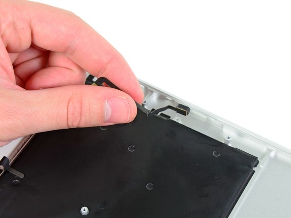
Utilisez l'extrémité plate d'une spatule (spudger) pour faire levier sur les deux côtés courts du connecteur de la batterie afin de le déconnecter de sa prise sur la carte mère.
-
Repliez légèrement la nappe de la batterie pour l'éloigner de la carte mère pour éviter que le connecteur ne se rabatte accidentellement et n'entre en contact avec sa prise.
-
-
Cette étape n’est pas traduite. Aidez à la traduire
-
Use the flat end of a spudger to pry the left and right I/O board cable connectors up off their respective sockets on the I/O board.
-
-
Cette étape n’est pas traduite. Aidez à la traduire
-
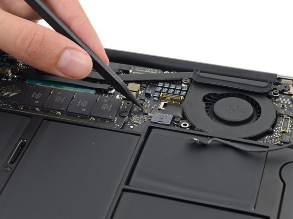
Use the tip of a spudger to carefully push on each side of the iSight camera cable connector to loosen it out of its socket on the logic board.
-
-
Cette étape n’est pas traduite. Aidez à la traduire
-
Peel the iSight camera cable up off the adhesive securing it to the fan.
-
-
Cette étape n’est pas traduite. Aidez à la traduire
-
Use the tip of a spudger to carefully flip up the retaining flap on the fan cable ZIF socket.
-
-
Cette étape n’est pas traduite. Aidez à la traduire
-
Remove the following three screws securing the fan to the upper case:
-
Two 5.5 mm T5 Torx screws
-
One 4.6 mm T5 Torx screw
-
-
Cette étape n’est pas traduite. Aidez à la traduire
-
Lift, but do not remove the fan out of its recess in the upper case.
-
Carefully pull the fan ribbon cable out of its socket as you remove the fan from the Air.
-
-
Cette étape n’est pas traduite. Aidez à la traduire
-
Use the flat end of a spudger to pry both antenna connectors up from their sockets on the AirPort/Bluetooth card, and move them out of the way.
-
-
Cette étape n’est pas traduite. Aidez à la traduire
-
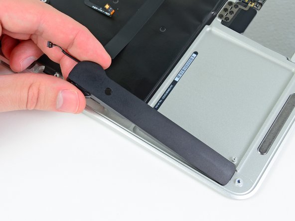
Remove the following five screws securing the battery to the upper case:
-
Two 5.2 mm T5 Torx screws
-
One 6 mm T5 Torx screw
-
Two 2.6 mm T5 Torx screws
-
-
Cette étape n’est pas traduite. Aidez à la traduire
-
Lift the battery from its edge nearest the logic board and remove it from the upper case.
-
-
Cette étape n’est pas traduite. Aidez à la traduire
-
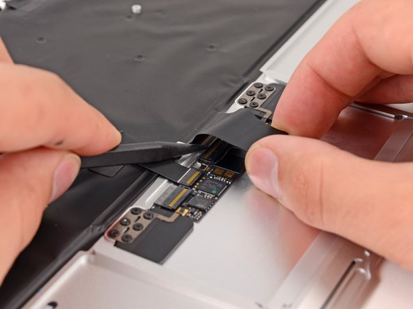
Disconnect the I/O board by pulling the power cable away from its socket on the logic board.
-
-
-
Cette étape n’est pas traduite. Aidez à la traduire
-
Use the tip of a spudger to de-route the antenna cables from their notches in the logic board.
-
-
Cette étape n’est pas traduite. Aidez à la traduire
-
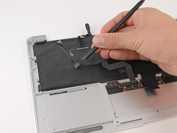
Gently push the tip of a spudger under the black plastic flap stuck to the display data cable lock to make the lock pop upward and away from the socket.
-
While holding the lock away from the socket, gently pull the display data cable out of its socket.
-
-
Cette étape n’est pas traduite. Aidez à la traduire
-
Use the tip of a spudger to pry under the speaker cable connector, lifting it straight up from its socket.
-
De-route the cable from its notch in the logic board.
-
-
Cette étape n’est pas traduite. Aidez à la traduire
-
Use the tip of a spudger or your fingernail to flip up the retaining flap on the trackpad ribbon cable ZIF socket.
-
Pull the trackpad ribbon cable straight out of its socket toward the front edge of the Air.
-
-
Cette étape n’est pas traduite. Aidez à la traduire
-
Use the tip of a spudger to flip up the retaining flap on the keyboard backlight ribbon cable ZIF socket.
-
Pull the keyboard backlight ribbon cable out of its socket.
-
-
Cette étape n’est pas traduite. Aidez à la traduire
-
Remove the single 2.9 mm T5 Torx screw securing the AirPort/Bluetooth card to the logic board.
-
-
Cette étape n’est pas traduite. Aidez à la traduire
-
Slightly lift the free end of the AirPort/Bluetooth board and pull it out of its socket on the logic board.
-
-
Cette étape n’est pas traduite. Aidez à la traduire
-
Remove the three 3.6 mm T5 Torx screws securing the logic board to the upper case.
-
In some models these are 3.1 mm T5 Torx screws.
-
-
Cette étape n’est pas traduite. Aidez à la traduire
-
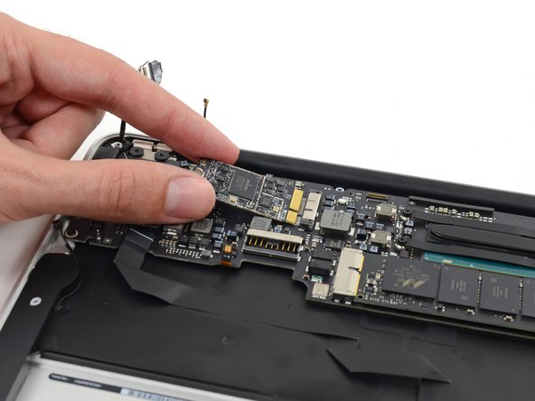
Gently lift the logic board assembly from the heat sink end and pull it away from the port side of the case to remove it from the Air.
-
-
Cette étape n’est pas traduite. Aidez à la traduire
-
Remove the small rubber gasket from the corner of the upper case nearest the the I/O board.
-
Remove the gasket from the corner nearest display cable connector.
-
-
Cette étape n’est pas traduite. Aidez à la traduire
-
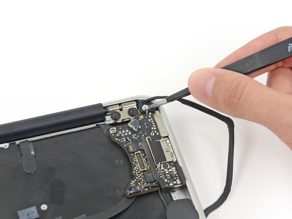
Use the tip of a spudger to carefully flip up the retaining flap on the microphone cable ZIF socket.
-
With a pair of tweezers, pull the microphone ribbon cable straight out of its socket.
-
-
Cette étape n’est pas traduite. Aidez à la traduire
-
Use the tip of a spudger to pry under the speaker cable near the connector, lifting it straight up from its socket.
-
De-route the cable from its notch in the logic board.
-
-
Cette étape n’est pas traduite. Aidez à la traduire
-
Remove the single 3.6 mm T5 Torx screw securing the I/O board to the upper case.
-
-
Cette étape n’est pas traduite. Aidez à la traduire
-
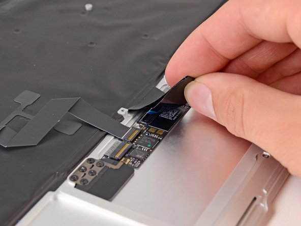
Carefully lift the I/O board by its power cable and pull it away from the edge of the case.
-
-
Cette étape n’est pas traduite. Aidez à la traduire
-
Peel up the six cable loops securing the antenna cables to the upper case.
-
Gently pull the cable loops slightly out of the channel cut into the upper case one at a time.
-
Use your spudger to open up the plastic loops as you de-route the antenna cables through them.
-
-
Cette étape n’est pas traduite. Aidez à la traduire
-
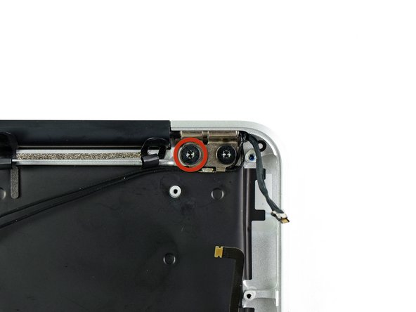
Remove the inner 4.9 mm T8 Torx screw securing each display hinge to the upper case (two screws total).
-
-
Cette étape n’est pas traduite. Aidez à la traduire
-
While holding the Air steady, remove the remaining 4.9 mm T8 Torx screw from the lower display bracket.
-
-
Cette étape n’est pas traduite. Aidez à la traduire
-
Remove the last 4.9 mm T8 Torx screw securing the display to the upper case.
-
-
Cette étape n’est pas traduite. Aidez à la traduire
-
Push the upper case slightly toward the display assembly, then rotate it away from the front of the display assembly.
-
Once the two display hinges have cleared the upper case, remove the display.
-
-
Cette étape n’est pas traduite. Aidez à la traduire
-
Use the flat end of a spudger to pry the right speaker off the adhesive securing it to the upper case.
-
Remove the right speaker from the upper case.
-
-
Cette étape n’est pas traduite. Aidez à la traduire
-
Use the flat end of a spudger to pry the left speaker off the adhesive securing it to the upper case.
-
Remove the left speaker from the upper case.
-
-
Cette étape n’est pas traduite. Aidez à la traduire
-
Use the tip of a spudger to pry the microphone away from the side of the upper case.
-
Remove the microphone from the upper case.
-
Upper case remains.
-
-
Cette étape n’est pas traduite. Aidez à la traduire
-
Push/lift the keyboard ribbon cable off of the upper case with one hand.
-
With the other hand, use a spudger to flip up the retaining flap on the ZIF connector.
-
Once the retaining flap has been flipped up, carefully pull the ribbon cable straight out of its socket.
-
-
Cette étape n’est pas traduite. Aidez à la traduire
-
Use the flat end of a spudger to separate the trackpad ribbon cable from the underside of the keyboard.
-
-
Cette étape n’est pas traduite. Aidez à la traduire
-
Remove the six 1.5 mm Phillips #00 screws securing the trackpad to the upper case.
-
Check your replacement upper case—if it doesn't have this wide T5 screw, remove it to transfer into the replacement.
-
-
Cette étape n’est pas traduite. Aidez à la traduire
-
Holding the upper case up off the table with one hand, gently push the trackpad up through the upper case.
-
Remove the trackpad from the upper case.
-


Annulation : je n'ai pas terminé ce tutoriel.
13 autres ont terminé cette réparation.


7 commentaires
Steps 20 and 21 are necessary, as there is a logic board screw slightly hidden underneath the Wireless Card, as you can see in Step 22.
The isight cable in the top right corner: I don’t think yours is installed right, it shouldn’t be going over that rubber grommet, it should be going to the left. Your cable is all stretched. I don’t see why steps 20 and 21 would be necessary, except temporarily to remove the screw. Step 31: My inners are T9 and my outers are T10. Also, I wouldn’t rate this as a 3-bar difficult. There isn’t even anything glued in, you don’t need a heat gun or adhesive remover, no special tools besides the pentalobe bit are required. Estimated time 30-60 minutes.
Steps 20 and 21 are necessary, as there is a logic board screw slightly hidden underneath the Wireless Card, as you can see in Step 22.
I completed this process in hopes that I would have repaired a power button problem on this MacBook Air. This didn’t seem to work. Any other suggestions. Could it be the logic board? Just trying to find some answers. Wonderful step by step guide, though…Kudos to all involved.