Cette version peut contenir des modifications incorrectes. Passez au dernier aperçu vérifié.
Ce dont vous avez besoin
-
-
Dévissez les dix vis suivantes :
-
Deux vis Pentalobe 5 points de 8 mm
-
Huit vis Pentalobe 5 points de 2,5 mm
-
-
Cette étape n’est pas traduite. Aidez à la traduire
-
Use the flat end of a spudger to pry both short sides of the battery connector upward to disconnect it from its socket on the logic board.
-
Bend the battery cable slightly away from the logic board so the connector will not accidentally contact its socket.
-
-
Cette étape n’est pas traduite. Aidez à la traduire
-
Remove the single 2.9 mm T5 Torx screw securing the SSD to the logic board.
-
-
Cette étape n’est pas traduite. Aidez à la traduire
-
Use a spudger to help lift the free end of the SSD just enough to grab it with your other hand.
-
Pull the drive straight out of its socket and remove it from the logic board.
-
-
Cette étape n’est pas traduite. Aidez à la traduire
-
Use the flat end of a spudger to pry the I/O board cable connector upward out of its socket on the I/O board.
-
-
Cette étape n’est pas traduite. Aidez à la traduire
-
While gently pulling the I/O board cable upward near its connection to the logic board, use the tip of a spudger to pry upward on alternating sides of the connector to help "walk" it out of its socket.
-
Remove the I/O board cable.
-
-
Cette étape n’est pas traduite. Aidez à la traduire
-
Use the tip of a spudger to carefully flip up the retaining flap on the fan cable ZIF socket.
-
-
Cette étape n’est pas traduite. Aidez à la traduire
-
Remove the following three screws securing the fan to the upper case:
-
Two 5.2 mm T5 Torx screws
-
One 3.6 mm T5 Torx screw
-
-
Cette étape n’est pas traduite. Aidez à la traduire
-
Lift the fan out of the upper case and carefully pull the fan ribbon cable out of its socket as you remove it from the Air.
-
-
-
À l'aide de l'extrémité plate d'un spudger, faites levier sur les deux côtés courts du connecteur de la batterie pour le débrancher de sa prise sur la carte mère.
-
Éloignez légèrement la nappe de la batterie de la carte mère afin d'éviter que le connecteur ne touche sa prise par accident .
-
-
-
Soulevez la batterie en la saisissant par le bord le plus proche de la carte mère et retirez-la du boîtier supérieur.
-
Chargez-la à 100%, puis laissez-la charger encore au moins deux heures. Utilisez votre appareil normalement. Lors de l'avertissement de batterie faible, enregistrez votre travail et laisser votre ordinateur allumé jusqu'à ce qu'il s'éteint à cause d'une batterie vide. Attendez au moins 5 heures, puis rechargez la batterie à 100% sans interruption.
-
Si vous remarquez quelques chose d'inhabituel ou si vous avez des problèmes après l'installation de la nouvelle batterie, il se peut que vous deviez peut-être réinitialiser le SMC de votre MacBook.
-
-
Cette étape n’est pas traduite. Aidez à la traduire
-
Disconnect the I/O board by pulling the power cable away from its socket on the logic board.
-
-
-
Cette étape n’est pas traduite. Aidez à la traduire
-
Use the tip of a spudger or your fingernail to flip up the retaining flap on the trackpad ribbon cable ZIF socket.
-
Pull the trackpad ribbon cable straight out of its socket toward the front edge of the Air.
-
-
Cette étape n’est pas traduite. Aidez à la traduire
-
Use the tip of a spudger to de-route the right speaker cable from the slot cut into the logic board.
-
-
Cette étape n’est pas traduite. Aidez à la traduire
-
Use the flat end of a spudger to pry the right speaker cable connector up and out of its socket on the logic board.
-
-
Cette étape n’est pas traduite. Aidez à la traduire
-
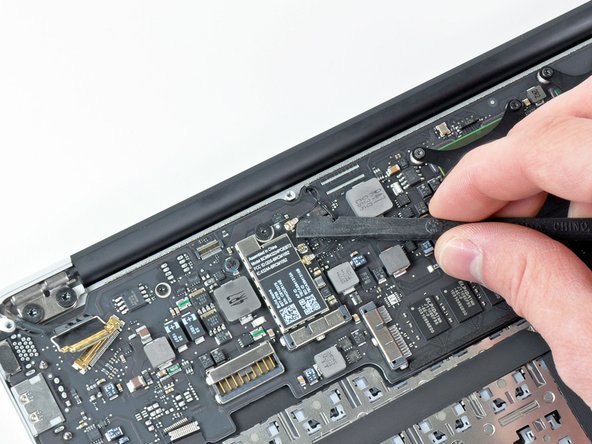
Gently push the tip of a spudger under the black plastic flap stuck to the display data cable lock to make the lock pop upward and away from the socket.
-
While holding the lock away from the socket, use the tip of a spudger and your fingers to gently remove the display data cable from its socket.
-
-
Cette étape n’est pas traduite. Aidez à la traduire
-
Remove the small rubber gasket from the corner of the upper case near the display data cable.
-
-
Cette étape n’est pas traduite. Aidez à la traduire
-
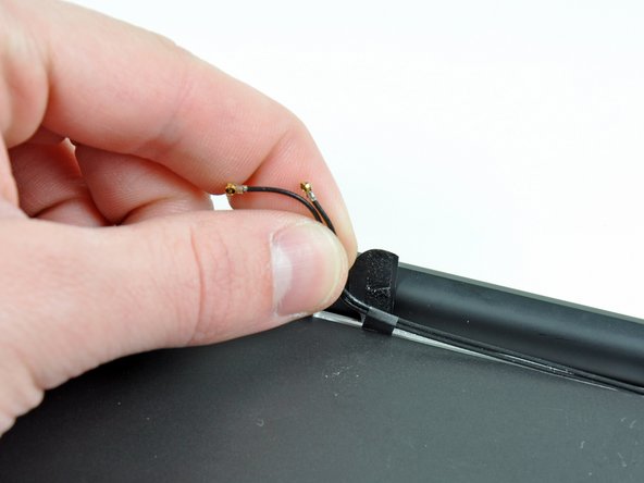
Use the flat end of a spudger to pry both antenna cable connectors up and off their sockets on the AirPort/Bluetooth card.
-
-
Cette étape n’est pas traduite. Aidez à la traduire
-
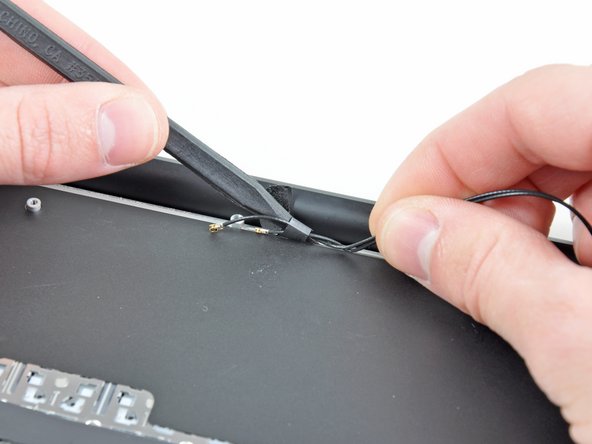
Gently de-route the antenna cables from the slot cut into the logic board.
-
-
Cette étape n’est pas traduite. Aidez à la traduire
-
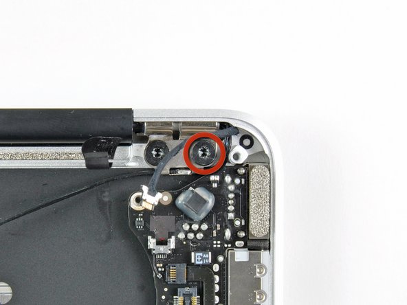
Remove the three 3.6 mm T5 Torx screws securing the logic board to the upper case.
-
-
Cette étape n’est pas traduite. Aidez à la traduire
-
Gently lift the logic board assembly out of the upper case, minding the fragile heat sink and any cables that may get caught.
-
-
Cette étape n’est pas traduite. Aidez à la traduire
-
Pull the camera cable parallel to the face of the I/O board toward the rear edge of the Air to disconnect it from its socket.
-
-
Cette étape n’est pas traduite. Aidez à la traduire
-
Remove the small rubber gasket from the corner of the upper case nearest the I/O board.
-
-
Cette étape n’est pas traduite. Aidez à la traduire
-
Peel up the six cable loops securing the antenna cables to the upper case.
-
Gently pull the cable loops slightly out of the channel cut into the upper case one at a time.
-
Use your spudger to open up the plastic loops as you de-route the antenna cables through them.
-
Repeat this for all five retaining loops.
-
-
Cette étape n’est pas traduite. Aidez à la traduire
-
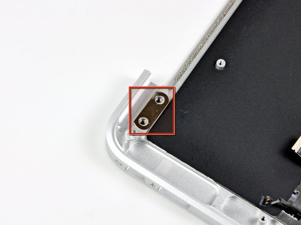
Remove the outer 4.9 mm T8 Torx screw securing each display hinge to the upper case (two screws total).
-
-
Cette étape n’est pas traduite. Aidez à la traduire
-
Open the display until it is perpendicular to the upper case and place it on a table as shown.
-
While holding the Air steady, remove the remaining 4.9 mm T8 Torx screw from the lower display bracket.
-
-
Cette étape n’est pas traduite. Aidez à la traduire
-
Remove the last 4.9 mm T8 Torx screw securing the display to the upper case.
-
-
Cette étape n’est pas traduite. Aidez à la traduire
-
Push the upper case slightly toward the display assembly, then rotate it away from the front of the display assembly.
-
Once the two display hinges have cleared the upper case, remove the display and set it aside.
-
-
Cette étape n’est pas traduite. Aidez à la traduire
-
Use the flat end of a spudger to pry the right speaker off the adhesive securing it to the upper case.
-
Remove the right speaker from the upper case.
-
-
Cette étape n’est pas traduite. Aidez à la traduire
-
Use the tip of a spudger to carefully flip up the retaining flap on the microphone cable ZIF socket.
-
Pull the microphone ribbon cable straight out of its socket.
-
-
Cette étape n’est pas traduite. Aidez à la traduire
-
Use the flat end of a spudger to pry the left speaker cable connector up and out of its socket on the I/O board.
-
De-route the left speaker cable from the notch cut into the I/O board.
-
-
Cette étape n’est pas traduite. Aidez à la traduire
-
Remove the single 3.6 mm T5 Torx screw securing the I/O board to the upper case.
-
-
Cette étape n’est pas traduite. Aidez à la traduire
-
Carefully lift the I/O board from its edge nearest the logic board and remove it from the upper case.
-
-
Cette étape n’est pas traduite. Aidez à la traduire
-
Use the flat end of a spudger to pry the left speaker off the adhesive securing it to the upper case.
-
Remove the left speaker from the upper case.
-
-
Cette étape n’est pas traduite. Aidez à la traduire
-
Use the tip of a spudger to pry the microphone away from the side of the upper case.
-
Remove the microphone from the upper case.
-
Upper case remains.
-
-
Cette étape n’est pas traduite. Aidez à la traduire
-
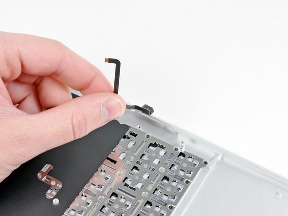
Use the tip of a spudger to pry up the retaining flap on the trackpad data cable ZIF connector.
-
Gently slide the trackpad ribbon cable out of the ZIF connector.
-
-
Cette étape n’est pas traduite. Aidez à la traduire
-
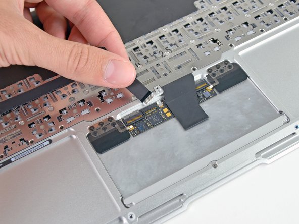
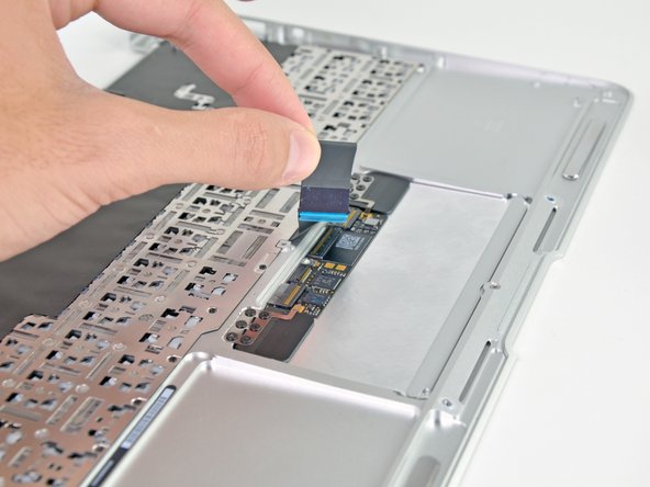
With one hand, lift the keyboard ribbon cable up and push it slightly away from the trackpad to access the ZIF connector underneath.
-
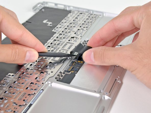
Use a spudger tip to pry up the retaining flap on the keyboard ribbon cable ZIF connector.
-
Gently slide the keyboard ribbon cable out of the ZIF connector.
-
-
Cette étape n’est pas traduite. Aidez à la traduire
-
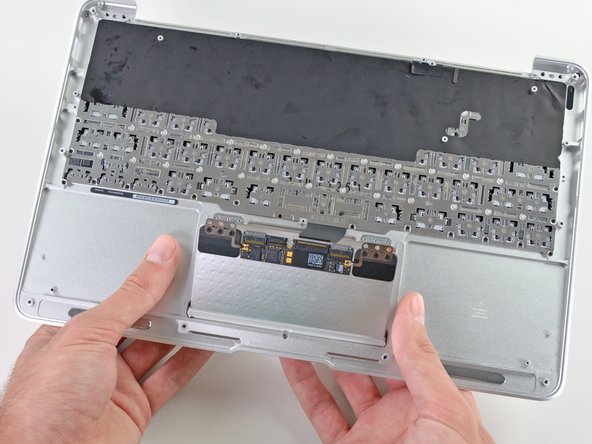
Remove the six 1.5 mm Phillips #00 screws that secure the trackpad assembly to the upper case.
-
-
Cette étape n’est pas traduite. Aidez à la traduire
-
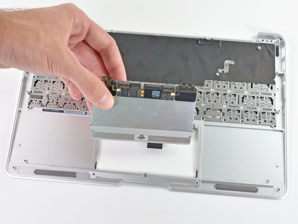
While supporting the upper case, press up on the side of the trackpad closest to the logic board.
-
Remove the trackpad.
-


Annulation : je n'ai pas terminé ce tutoriel.
28 autres ont terminé cette réparation.


3 commentaires
There is a T5 screw-thing in the upper case below the track pad. Adjusting this changes the play in the track pad 'click', though be careful since nothing stops it from being screwed too far in. It's not mentioned in the guide, but if you're replacing the upper case you will want to make sure the screw is installed and adjusted to your clicking taste!
netherby makes a good point about the tension screw for the trackpad!
This is a funny headless screw which goes in between the trackpad and the edge of the upper case. I pulled the trackpad from the old case without noticing this, reassembled to find the trackpad all weirdly loose. Tension screw fixed it.
The hard case is great for putting in my backpack and not worrying about the computer getting damaged. http://bestapplecases.com/best-macbook-a...