Cette version peut contenir des modifications incorrectes. Passez au dernier aperçu vérifié.
Ce dont vous avez besoin
-
-
Retirez les dix vis suivantes :
-
Deux vis pentalobes 8 mm 5-points
-
Huit vis pentalobes 2.5 mm 5-points
-
-
-
Utilisez l'extrémité plate d'un spudger pour faire levier sur les deux côtés courts du connecteur de la batterie et débrancher celui-ci de sa prise sur la carte mère.
-
Repliez légèrement la nappe de la batterie hors de la carte mère afin que le connecteur ne contacte pas accidentellement sa prise.
-
-
Cette étape n’est pas traduite. Aidez à la traduire
-
Use the flat end of a spudger to pry the I/O board cable up from its socket on the I/O board.
-
-
Cette étape n’est pas traduite. Aidez à la traduire
-
Peel the I/O board cable up from the adhesive securing it to the fan.
-
-
Cette étape n’est pas traduite. Aidez à la traduire
-
Use the flat end of a spudger to lift the I/O board connector up and out of its socket on the logic board
-
Remove the I/O board cable.
-
-
Cette étape n’est pas traduite. Aidez à la traduire
-
Use the tip of a spudger to carefully flip up the retaining flap on the fan cable ZIF socket.
-
-
Cette étape n’est pas traduite. Aidez à la traduire
-
Remove the following three screws securing the fan to the upper case:
-
Two 5.2 mm T5 Torx screws
-
One 3.6 mm T5 Torx screw
-
-
Cette étape n’est pas traduite. Aidez à la traduire
-
Lift the fan out of the upper case and carefully pull the fan ribbon cable out of its socket as you remove it from the Air.
-
-
Cette étape n’est pas traduite. Aidez à la traduire
-
Remove the following five screws securing the battery to the upper case:
-
Two 5.2 mm T5 Torx screws
-
One 6 mm T5 Torx screw
-
Two 2.6 mm T5 Torx screws
-
-
Cette étape n’est pas traduite. Aidez à la traduire
-
Lift the battery from its edge nearest the logic board and remove it from the upper case.
-
-
Cette étape n’est pas traduite. Aidez à la traduire
-
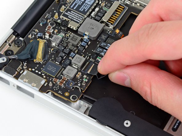
Use the flat end of a spudger to free the adhesive loop securing the I/O board power cable to the upper case.
-
Disconnect the I/O board by pulling the power cable away from its socket on the logic board.
-
-
Cette étape n’est pas traduite. Aidez à la traduire
-
Use the tip of a spudger to flip up the retaining flap on the keyboard backlight ribbon cable ZIF socket.
-
Pull the keyboard backlight ribbon cable out of its socket.
-
-
-
Cette étape n’est pas traduite. Aidez à la traduire
-
Use the tip of a spudger or your fingernail to flip up the retaining flap on the trackpad ribbon cable ZIF socket.
-
Pull the trackpad ribbon cable straight out of its socket toward the front edge of the Air.
-
-
Cette étape n’est pas traduite. Aidez à la traduire
-
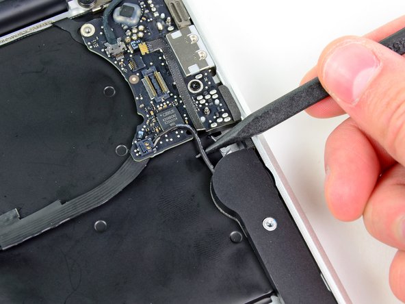
Use the tip of a spudger to de-route the right speaker cable from the slot cut into the logic board.
-
-
Cette étape n’est pas traduite. Aidez à la traduire
-
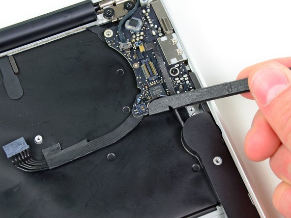
Use the flat end of a spudger to pry the right speaker cable connector up and out of its socket on the logic board.
-
-
Cette étape n’est pas traduite. Aidez à la traduire
-
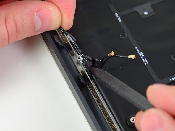
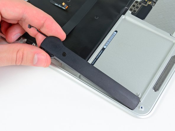
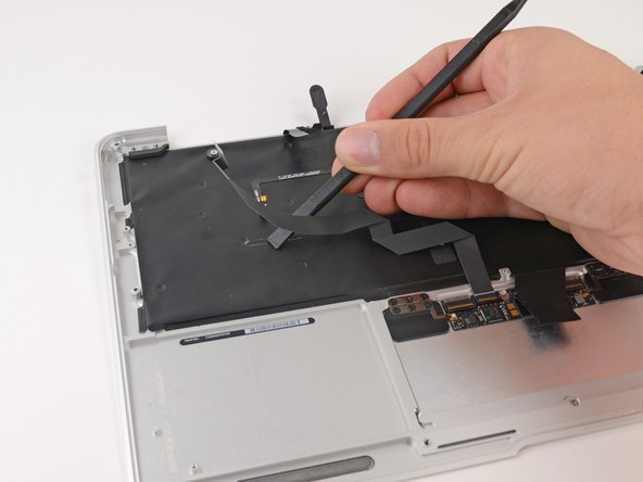
Gently push the tip of a spudger under the black plastic flap stuck to the display data cable lock to make the lock pop upward and away from the socket.
-
Remove the small rubber gasket from the corner of the upper case near the display data cable.
-
-
Cette étape n’est pas traduite. Aidez à la traduire
-
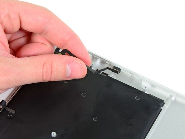
While holding the lock away from the socket, gently pull the display data cable out of its socket.
-
-
Cette étape n’est pas traduite. Aidez à la traduire
-
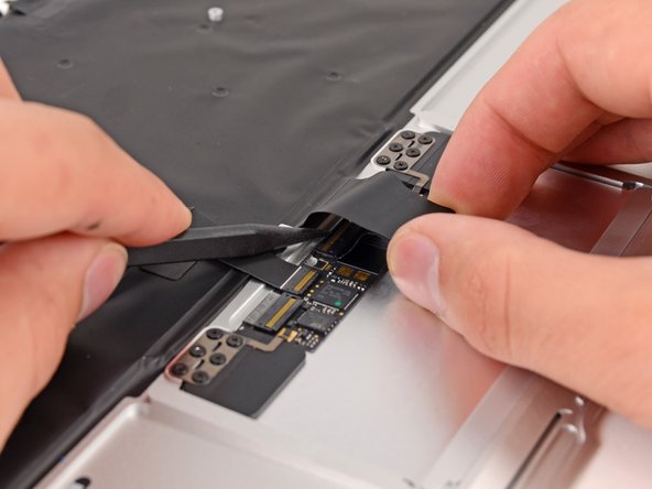
Use the flat end of a spudger to pry both antenna cable connectors up and off their sockets on the AirPort/Bluetooth card.
-
-
Cette étape n’est pas traduite. Aidez à la traduire
-
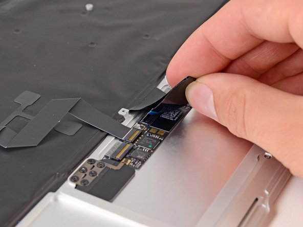
Gently de-route the antenna cables from the slot cut into the logic board.
-
-
Cette étape n’est pas traduite. Aidez à la traduire
-
Remove the three 3.6 mm T5 Torx screws securing the logic board to the upper case.
-
-
Cette étape n’est pas traduite. Aidez à la traduire
-
Gently lift the logic board assembly out of the upper case, minding the fragile heat sink and any cables that may get caught.
-
-
Cette étape n’est pas traduite. Aidez à la traduire
-
Remove the small rubber gasket from the corner of the upper case nearest the I/O board.
-
-
Cette étape n’est pas traduite. Aidez à la traduire
-
Use the tip of a spudger to carefully flip up the retaining flap on the microphone cable ZIF socket.
-
Pull the microphone ribbon cable straight out of its socket.
-
-
Cette étape n’est pas traduite. Aidez à la traduire
-
De-route the left speaker cable from the notch cut into the I/O board.
-
Use the flat end of a spudger to pry the left speaker cable connector up and out of its socket on the I/O board.
-
-
Cette étape n’est pas traduite. Aidez à la traduire
-
Pull the camera cable parallel to the face of the I/O board toward the rear edge of the Air to disconnect it from its socket.
-
-
Cette étape n’est pas traduite. Aidez à la traduire
-
Remove the single 3.6 mm T5 Torx screw securing the I/O board to the upper case.
-
-
Cette étape n’est pas traduite. Aidez à la traduire
-
Carefully lift the I/O board from its edge nearest the logic board and remove it from the upper case.
-
-
Cette étape n’est pas traduite. Aidez à la traduire
-
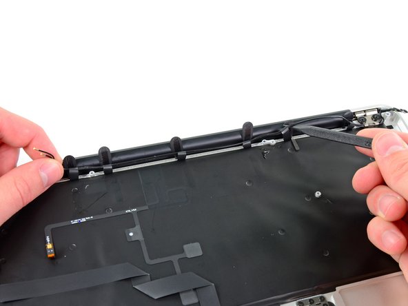
Peel up the six cable loops securing the antenna cables to the upper case.
-
Gently pull the cable loops slightly out of the channel cut into the upper case one at a time.
-
Use your spudger to open up the plastic loops as you de-route the antenna cables through them.
-
Repeat this for all of the retaining loops.
-
-
Cette étape n’est pas traduite. Aidez à la traduire
-
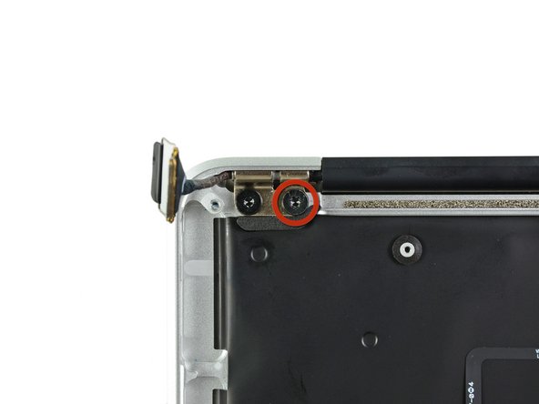
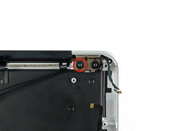
Remove the inner 4.9 mm T8 Torx screw securing each display hinge to the upper case (two screws total).
-
-
Cette étape n’est pas traduite. Aidez à la traduire
-
Open the display until it is perpendicular to the upper case and place it on a table as shown.
-
While holding the Air steady, remove the remaining 4.9 mm T8 Torx screw from the lower display bracket.
-
-
Cette étape n’est pas traduite. Aidez à la traduire
-
Remove the last 4.9 mm T8 Torx screw securing the display to the upper case.
-
-
Cette étape n’est pas traduite. Aidez à la traduire
-
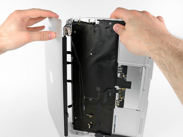
Push the upper case slightly toward the display assembly, then rotate it away from the front of the display assembly.
-
Once the two display hinges have cleared the upper case, remove the display and set it aside.
-
-
Cette étape n’est pas traduite. Aidez à la traduire
-
Use the flat end of a spudger to pry the right speaker off the adhesive securing it to the upper case.
-
Remove the right speaker from the upper case.
-
-
Cette étape n’est pas traduite. Aidez à la traduire
-
Use the flat end of a spudger to pry the left speaker off the adhesive securing it to the upper case.
-
Remove the left speaker from the upper case.
-
-
Cette étape n’est pas traduite. Aidez à la traduire
-
Use the tip of a spudger to pry the microphone away from the side of the upper case.
-
Remove the microphone from the upper case.
-
Upper case remains.
-
-
Cette étape n’est pas traduite. Aidez à la traduire
-
Push/lift the keyboard ribbon cable off of the upper case with one hand.
-
With the other hand, use a spudger to flip up the retaining flap on the ZIF connector.
-
Once the retaining flap has been flipped up, carefully pull the ribbon cable straight out of its socket.
-
-
Cette étape n’est pas traduite. Aidez à la traduire
-
Use the flat end of a spudger to separate the trackpad ribbon cable from the underside of the keyboard.
-
-
Cette étape n’est pas traduite. Aidez à la traduire
-
Remove the six 1.5 mm Phillips #00 screws securing the trackpad to the upper case.
-
Check your replacement upper case—if it doesn't have this wide T5 screw, remove it to transfer into the replacement.
-
-
Cette étape n’est pas traduite. Aidez à la traduire
-
Holding the upper case up off the table with one hand, gently push the trackpad up through the upper case.
-
Remove the trackpad from the upper case.
-


Annulation : je n'ai pas terminé ce tutoriel.
44 autres ont terminé cette réparation.


8 commentaires
I used this guide to replace the keyboard on my macbook air 11, mid 2011.
When I removed the perimeter screws on the keyboard, I then popped all of the 54 or so rivots. I bought a $34 keyboard and installed it with the perimeter screws. But then I bonded the top of each of the rivot shafts with a tiny amount of epoxy cement, after which I used a razor blade to shave each of them to be flush. After re-installing the backlight material, and reassembling the computer, it works PERFECTLY. The Apple store expert had told us that the computer could not be repaired. :-)
I’ve bought a replacement keyboard with holes in every place where a rivot existed. So it doesn’t requires any work on the case for the remains of the rivots.
Thank you very much for your clear guide! Even though I had never opened a laptop before, I was able to dig down to my keyboard with your instructions and I'm typing this now with BOTH shift keys :-D
Note: unlike @Bill Aldridge I bought extra screws to replace the rivets and replaced all but four of the rivets using (at my Father's suggestion) flat sharp wire cutters to bite into the stumps of the rivets and then pop them out.