Cette version peut contenir des modifications incorrectes. Passez au dernier aperçu vérifié.
Ce dont vous avez besoin
-
-
Retirez les dix vis suivantes :
-
Deux vis pentalobes 8 mm 5-points
-
Huit vis pentalobes 2.5 mm 5-points
-
-
-
Utilisez l'extrémité plate d'une spatule (spudger) pour faire levier sur les deux côtés courts du connecteur de la batterie afin de le déconnecter de sa prise sur la carte mère.
-
Repliez légèrement la nappe de la batterie pour l'éloigner de la carte mère pour éviter que le connecteur ne se rabatte accidentellement et n'entre en contact avec sa prise.
-
-
Cette étape n’est pas traduite. Aidez à la traduire
-
Use the flat end of a spudger to pry the left and right I/O board cable connectors up off their respective sockets on the I/O board.
-
-
Cette étape n’est pas traduite. Aidez à la traduire
-
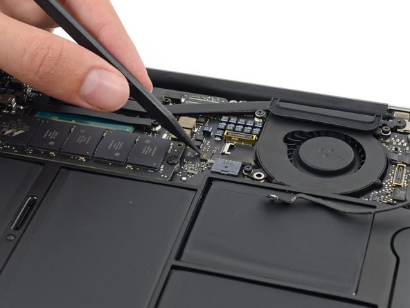
Use the tip of a spudger to carefully push on each side of the iSight camera cable connector to loosen it out of its socket on the logic board.
-
-
Cette étape n’est pas traduite. Aidez à la traduire
-
Peel the iSight camera cable up off the adhesive securing it to the fan.
-
-
Cette étape n’est pas traduite. Aidez à la traduire
-
Use the tip of a spudger to carefully flip up the retaining flap on the fan cable ZIF socket.
-
-
Cette étape n’est pas traduite. Aidez à la traduire
-
Remove the following three screws securing the fan to the upper case:
-
Two 5.5 mm T5 Torx screws
-
One 4.6 mm T5 Torx screw
-
-
-
Cette étape n’est pas traduite. Aidez à la traduire
-
Lift, but do not remove the fan out of its recess in the upper case.
-
Carefully pull the fan ribbon cable out of its socket as you remove the fan from the Air.
-
-
Cette étape n’est pas traduite. Aidez à la traduire
-
Use the flat end of a spudger to pry both antenna connectors up from their sockets on the AirPort/Bluetooth card, and move them out of the way.
-
-
Cette étape n’est pas traduite. Aidez à la traduire
-
Remove the following five screws securing the battery to the upper case:
-
Two 5.2 mm T5 Torx screws
-
One 6 mm T5 Torx screw
-
Two 2.6 mm T5 Torx screws
-
-
Cette étape n’est pas traduite. Aidez à la traduire
-
Lift the battery from its edge nearest the logic board and remove it from the upper case.
-
-
Cette étape n’est pas traduite. Aidez à la traduire
-
Disconnect the I/O board by pulling the power cable away from its socket on the logic board.
-
-
Cette étape n’est pas traduite. Aidez à la traduire
-
Use the tip of a spudger to de-route the antenna cables from their notches in the logic board.
-
-
Cette étape n’est pas traduite. Aidez à la traduire
-
Gently push the tip of a spudger under the black plastic flap stuck to the display data cable lock to make the lock pop upward and away from the socket.
-
While holding the lock away from the socket, gently pull the display data cable out of its socket.
-
-
Cette étape n’est pas traduite. Aidez à la traduire
-
Use the tip of a spudger to pry under the speaker cable connector, lifting it straight up from its socket.
-
De-route the cable from its notch in the logic board.
-
-
Cette étape n’est pas traduite. Aidez à la traduire
-
Use the tip of a spudger or your fingernail to flip up the retaining flap on the trackpad ribbon cable ZIF socket.
-
Pull the trackpad ribbon cable straight out of its socket toward the front edge of the Air.
-
-
Cette étape n’est pas traduite. Aidez à la traduire
-
Use the tip of a spudger to flip up the retaining flap on the keyboard backlight ribbon cable ZIF socket.
-
Pull the keyboard backlight ribbon cable out of its socket.
-
-
Cette étape n’est pas traduite. Aidez à la traduire
-
Remove the single 2.9 mm T5 Torx screw securing the AirPort/Bluetooth card to the logic board.
-
-
Cette étape n’est pas traduite. Aidez à la traduire
-
Slightly lift the free end of the AirPort/Bluetooth board and pull it out of its socket on the logic board.
-
-
Cette étape n’est pas traduite. Aidez à la traduire
-
Remove the three 3.6 mm T5 Torx screws securing the logic board to the upper case.
-
In some models these are 3.1 mm T5 Torx screws.
-
-
Cette étape n’est pas traduite. Aidez à la traduire
-
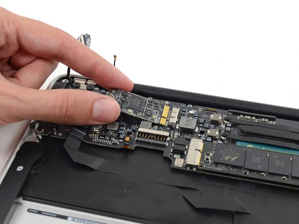
Gently lift the logic board assembly from the heat sink end and pull it away from the port side of the case to remove it from the Air.
-
-
Cette étape n’est pas traduite. Aidez à la traduire
-
Remove the four 2.5 mm T5 Torx screws securing the heat sink to the logic board.
-
-
Cette étape n’est pas traduite. Aidez à la traduire
-
If the heat sink seems to be stuck to the logic board after removing all four screws, use a spudger to carefully separate the heat sink from the faces of the CPU.
-
Remove the heat sink from the logic board.
-
When reinstalling the heat sink, be sure to apply a new layer of thermal paste. If you have never applied thermal paste before, we have a guide that makes it easy.
-
-
Cette étape n’est pas traduite. Aidez à la traduire
-
Remove the single 2.9 mm T5 Torx screw securing the SSD to the logic board.
-
-
Cette étape n’est pas traduite. Aidez à la traduire
-
Lift the free end of the SSD just enough to get a good hold of it.
-
Pull the drive straight out of its socket and remove it from the logic board.
-


Annulation : je n'ai pas terminé ce tutoriel.
31 autres ont terminé cette réparation.

