Cette version peut contenir des modifications incorrectes. Passez au dernier aperçu vérifié.
Ce dont vous avez besoin
-
-
Utilisez un tournevis P5 Pentalobe pour retirer les dix vis qui fixent le boîtier inférieur, dont les dimensions sont les suivantes :
-
Deux vis de 9 mm
-
Huit vis de 2,6 mm
-
-
-
Saisissez la languette en plastique transparent attachée au connecteur de la batterie, et tirez-la vers l'avant du MacBook Air pour déconnecter la batterie de la carte mère.
-
-
-
Avec l'extrémité plate d'une spatule (spudger), soulevez le connecteur de la nappe de la carte E/S hors de sa prise sur la carte E/S.
-
-
-
Avec la pointe d'une spatule, ouvrez soigneusement le clapet de retenue de la prise ZIF de la nappe du ventilateur.
-
-
-
Déconnectez la carte E/S en débranchant la nappe d'alimentation de sa prise sur la carte mère.
-
-
-
Cette étape n’est pas traduite. Aidez à la traduire
-
Remove the following five screws securing the battery to the upper case:
-
Three 6.3 mm T5 Torx screws
-
Two 2.4 mm T5 Torx screws
-
-
Cette étape n’est pas traduite. Aidez à la traduire
-
Lift the battery from its edge nearest the logic board and remove it from the upper case.
-
-
Cette étape n’est pas traduite. Aidez à la traduire
-
Use the tip of a spudger or your fingernail to flip up the retaining flap on the trackpad ribbon cable ZIF socket.
-
Be sure you are prying up on the hinged retaining flap, not the socket itself.
-
-
Cette étape n’est pas traduite. Aidez à la traduire
-
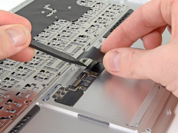
Use the tip of a spudger to flip up the retaining flap on the keyboard backlight ribbon cable ZIF socket.
-
Use your spudger to help pull the cable out of its socket.
-
-
Cette étape n’est pas traduite. Aidez à la traduire
-
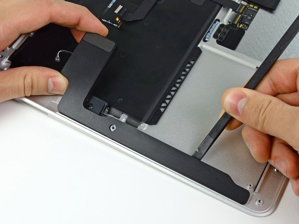
Use the flat end of a spudger to pry the right speaker cable connector up and out of its socket on the logic board.
-
-
Cette étape n’est pas traduite. Aidez à la traduire
-
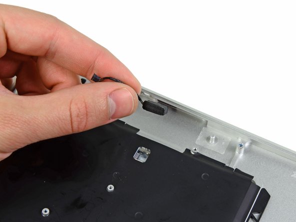
Gently push the tip of a spudger under the black plastic flap stuck to the display data cable lock to make the lock pop upward and away from the socket.
-
While holding the lock away from the socket, use the tip of a spudger and your fingers to gently remove the display data cable from its socket.
-
-
Cette étape n’est pas traduite. Aidez à la traduire
-
Use the flat end of a spudger to pry both antenna cable connectors up and off their sockets on the AirPort/Bluetooth card.
-
-
Cette étape n’est pas traduite. Aidez à la traduire
-
Gently de-route the antenna cables from the slot cut into the logic board.
-
-
Cette étape n’est pas traduite. Aidez à la traduire
-
Remove the single 2.85 mm T5 Torx screw securing the SSD to the logic board.
-
-
Cette étape n’est pas traduite. Aidez à la traduire
-
Pull the drive straight out of its socket and remove it from the logic board.
-
-
Cette étape n’est pas traduite. Aidez à la traduire
-
Remove the six 6.3 mm T5 Torx screws securing the logic board to the upper case.
-
-
Cette étape n’est pas traduite. Aidez à la traduire
-
Remove the inner two 4.9 mm T8 Torx screws securing the antenna cable retainer and left clutch hinge to the upper case.
-
-
Cette étape n’est pas traduite. Aidez à la traduire
-
Push the antenna cable retainer away slightly and remove the 3 mm T5 Torx screw securing the end of the heat sink to the upper case.
-
-
Cette étape n’est pas traduite. Aidez à la traduire
-
Carefully remove the logic board assembly from the upper case, minding any cables that may get caught.
-
-
Cette étape n’est pas traduite. Aidez à la traduire
-
Gently de-route the antenna cables out of the channel cut into the upper case.
-
-
Cette étape n’est pas traduite. Aidez à la traduire
-
Remove the inner two 4.9 mm T8 Torx screws securing the right display hinge to the upper case.
-
-
Cette étape n’est pas traduite. Aidez à la traduire
-
Open the display until it is perpendicular to the upper case and place it on a table as shown.
-
While holding the Air steady, remove the remaining 4.9 mm T8 Torx screw from the lower display bracket.
-
-
Cette étape n’est pas traduite. Aidez à la traduire
-
Remove the last 4.9 mm T8 Torx screw securing the display to the upper case.
-
-
Cette étape n’est pas traduite. Aidez à la traduire
-
Push the upper case slightly toward the display assembly, then rotate it away from the front of the display assembly.
-
Once the two display hinges have cleared the upper case, remove the display and set it aside.
-
-
Cette étape n’est pas traduite. Aidez à la traduire
-
Use the flat end of a spudger to pry the right speaker off the adhesive securing it to the upper case.
-
Remove the right speaker from the upper case.
-
-
Cette étape n’est pas traduite. Aidez à la traduire
-
Use the flat end of a spudger to pry the left speaker off the adhesive securing it to the upper case.
-
Remove the left speaker from the upper case.
-
-
Cette étape n’est pas traduite. Aidez à la traduire
-
Use the tip of a spudger to pry the microphone away from the left side of the upper case.
-
Remove the microphone from the upper case.
-
Upper case remains.
-
-
Cette étape n’est pas traduite. Aidez à la traduire
-
Use the tip of a spudger or your fingernail to flip up the retaining flap on the trackpad ribbon cable ZIF socket.
-
Pull the trackpad ribbon cable straight out of its socket toward the rear edge of the Air.
-
-
Cette étape n’est pas traduite. Aidez à la traduire
-
While carefully lifting the keyboard ribbon cable with one hand, use the tip of a spudger or your fingernail to flip up the retaining flap on the keyboard ribbon cable ZIF socket.
-
Pull the keyboard ribbon cable straight out of its socket toward the front edge of the Air.
-
-
Cette étape n’est pas traduite. Aidez à la traduire
-
Remove the following seven screws:
-
Six 1.6 mm Phillips screws securing the trackpad to the upper case.
-
One 1.4 mm T5 Torx set screw from its tapped hole near the front edge of the upper case.
-
-
Cette étape n’est pas traduite. Aidez à la traduire
-
Carefully lift the edge of the trackpad closest to the keyboard from its recess in the upper case by lifting it away from the brackets attached to the upper case.
-
Remove the trackpad from the upper case.
-
The upper case remains.
-


Annulation : je n'ai pas terminé ce tutoriel.
81 autres ont terminé cette réparation.

16 commentaires
question for anyone...just did step 14, and accidentally pried the whole microphone cable box out of the board. Any way to put that back in or did i just lose microphone capability?
You can resolder it back on or carefully use a hot-air rework station and Kapton tape to protect the surrounding area.
This guide is truly SPOT-on!!
I went to my local Fry's Electronics and purchased a Pro's Kit branded "Consumer Electronic Equipment Repair Kit" that had all the necessary bits and tools needed for US$35.
No need to spend $250 for a new upper case, I figured: what did I have to loose?
I found a brand new keyboard $45.95 (included priority shipping) from MCCComputers.com
Steps: Remove keyboard:: CAREFULLY, remove all #000 Philips head screws around the outside edge of the keyboard on the logic board side of top case. Then, i started at one end, four keys at a time and started rocking around the four corners and pressing firmly in sections (from the side where you usually type on the keys, inward) until the rivets started popping out. MAKE SURE YOU ARE DOING THIS IN AN ENVIRONMENT THAT IS CLEAN and SMOOTH SURFACES. They go everywhere!
Reassembly:use 3M #77 adhesive spray on the aluminum casing to reattach and make up for lost rivets. Snap in rivets with flat end of T-15 bit and screw-in edge screws.
Step 9
On reassembly with a new upper case I spent a long time trying to replace the red-circled screw to hold the fan. After a while I figured out that the new case I purchased from IFIXIT had a small screw already inserted in the socket. Once I removed this extra part everything went smoothly.
THAT’S why I ended up with an extra screw!
I agree, this guide is great. Was able to skip the last few steps, as my replacement upper case was already assembled.