Introduction
Pré-requis interne.
Ce dont vous avez besoin
-
-
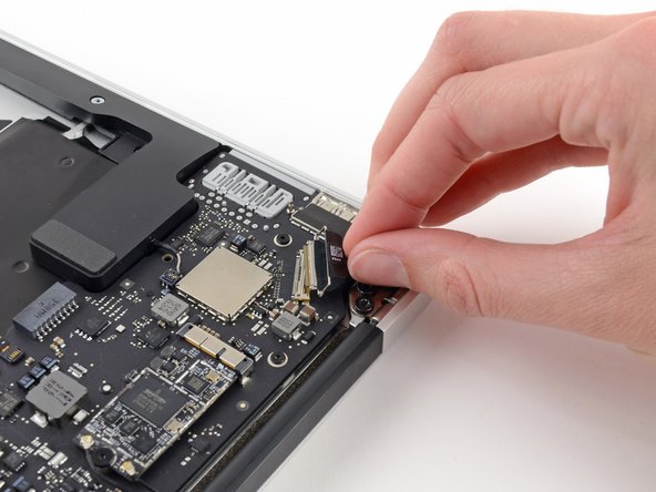
Saisissez la languette en plastique fixée au dispositif de verrouillage du câble de données de l'écran et faites-la pivoter vers le haut de l'ordinateur.
-
-
-
Utilisez l'extrémité plate d'un spudger pour retirer les deux connecteurs de câble d'antenne de leur prise sur la carte AirPort/Bluetooth.
One of my terminals is broken. What solutions do you recommend me
You’re actually pushing the connector from side to side toward the front of the case (or towards the track pad). It’s not a vertical motion at all.
I’d also mention to be careful taking these off and putting them back on. I also accidentally pulled a terminal off it’a cable.
If the process is taken to replace the top case, you can leave the AirPort card hanging from the antenna wires. Only remove the card’s retaining screw and slide the card to the right (direction of the antenna connectors) to separate it from the main board.
-
-
-
Débranchez le connecteur du câble de la caméra avec la pointe d'un spudger.
-
Tirez le câble de la caméra parallèlement à la surface de la carte E/S vers le bord avant de l'Air pour le sortir de sa prise.
You’ve missed a whole section here on removing the fan. It’s still present in Step 19 pics, but gone by Step 23. It’s not that it’s difficult to work out how to do it. But, when reassembling and following the steps in reverse, it’s handy to know when to use which screws!
Ah! –my bad. The steps for removing Fan etc. are there –up round Step 13. It’s just your photos that are slightly out of sync, as it’s back in place again by Step 19. So, while working in reverse, it looks like it’s not been covered.
On getting it on — i feel it's implied by the word "push” you can walk it out with the spudger. I couldn't wanage that, and instead walked it out by taking the cord between my index and thumb and walking it out by pulling it to the right and then the left repeatedly in a
-
-
-
-
Utilisez la pointe d'un spudger pour faire basculer le clapet de retenue de la prise ZIF nappe du rétro-éclairage du clavier.
-
Utilisez votre spudger pour retirer délicatement la nappe du rétro-éclairage du clavier hors de sa prise.
Do you know where i can buy the retaining clip ?
Not sure you can. I’d just use some kapton tape to hold it in place and call it good.
-
-
-
Utilisez l'extrémité plate d'un spudger pour faire levier sur le connecteur du haut-parleur droit et le retirer de sa prise sur la carte mère.
What is this cables for?
It’s a speaker cable
This is the one that gave me the hardest time!!! It does pop up and out tho.
-
-
-
Retirez les six vis Torx T5 de 6,3 mm fixant la carte mère au boîtier supérieur.
When re-assembling the motherboard, attach all 6 screws but do not completely tighten yet.
First make sure the rubber gasket is sitting properly, that the 7th screw hole (from Step 18) is properly aligned, and the Airport wire is sitting properly and also not caught under the heat sink.
Once everything is well aligned, start tightening the screws while watching out for the alignment. I found it useful to keep an eye on screw-hole from Step 18 as a reference.
Going in this order, there is a 7th screw securing the logic board to the frame; the heatsink is secured to the logic board with 4 screws, and secured to the frame with 1 more screw. Either take the heatsink off first, or remove that last screw underneath two small black wires, next to the left (as viewed when using the computer; if the computer is flipped over with the cover off and the monitor hinge end of the computer farthest from you, it is in the far right corner) set of three big torx screws that hold the hinge in place. The exact location of this screw is pictured in step 35's second picture; the screw goes through the loop visible below the rubber fan insulator. Scoot those 2 li'l wires out of the way and remove that screw, then the logic board comes right out. If this isn't clear, please let me know and I'll try to describe it better, or add a photo. If I'm posting this to the wrong instruction page, let me know; I was pretty sure I correctly identified my rig, but if not, sorry for the N00bage.
I got an extra screw hiding under the rubber gasket holding the end of the heatsink to the chassis. Ended up bending the heatsink a little cause I wasn't looking for it.
“Samsung RAM module”… do you mean the SSD? That stick of NVRAM is totally your hard drive.
Exactly, he means SSD (storage) the RAM (memory) is soldered to this 820-00165 logic board. Also on this model the 2015 MBA there is no logic board retaining screw under the SSD
-
-
-
Retirez les deux vis Torx intérieures de 4,9 mm fixant le dispositif de retenue du câble de l'antenne et la charnière gauche au boîtier.
This is the same screws as step 17.
Good catch! We did some sleuthing and it looks like a couple guides did indeed have an extra section of steps! All better now =)
In my computer these screws were the same size as the other side’s hinge screws. All 6 are the same size.
-
-
-
Éloignez légèrement le dispositif de retenue du câble de l'antenne et retirez la vis Torx T5 de 3 mm fixant l'extrémité du dissipateur thermique au boîtier supérieur.
It’s not clear what you mean by “This step is not needed.” If you want to remove the logic board from the upper case in order to put it onto your replacement upper case, you will have to remove this screw.
This step is only needed if you’re replacing the ENTIRE top case. Simply swapping out the trackpad unit does not make this step necessary. This entire tutorial assumes you’re replacing the entire top case which is an expensive mistake if you’re simply replacing the trackpad and/or keyboard. The keyboard is removable as well despite those many tiny rivets. Save money and time by not replacing the entire top case for a bad trackpad and/or keyboard. I needed to accomplish this step because I also removed and replaced the keyboard.
NOTE: There is a sort of clamp/washer attached to this screw that I didn’t know about until I flipped the laptop up on its side and it fell onto the desk. Also: you need to reset it *before* the motherboard
In my computer this screw was not there, nor was a related washer. I got it used so perhaps someone has already been there and did not replace the screw.
Also, the photo here shows how this end of the fan gasket is placed
.
-
-
-
Faites glisser l'extrémité plate d'un spudger sous le haut-parleur droit à partir de l'extrémité la plus proche de la charnière vers le bord avant de l'Air pour décoller l'adhésif.
-
Retirez le haut-parleur droit du boîtier supérieur.
You don’t really *have* to remove the speaker, especially if your replacement upper case assembly already includes the speakers.
I found the same. If you already have speakers in your new upper case, you can leave them. When you put the logic board back in, it will be a tight fit. I had to start with the corner near the right hinge (the Thunderbolt port corner) and work it in to place.
If it is difficult to remove the speakers you can use Isopropyl Alcohol to loosen the adhesive holding the speakers in place. Make sure to keep the Isopropyl Alcohol away from the speaker itself.
-
-
-
Retirez avec précaution l'ensemble carte mère du boîtier, en tenant compte des câbles pouvant rester accrochés.
-
Gardez les câbles détachés à l'écart de la carte afin qu'ils ne soient pas coincés en dessous.
-
Assurez-vous que les câbles d'antenne sont insérés dans leur encoche respective sur la carte mère, comme indiqué sur la seconde image.
It’s probably worth mentioning here that during reassembly you want to tuck the rubber gasket under the extension of the heat sink that the fan slots into.
-


Pour réassembler votre appareil, suivez ces instructions dans l'ordre inverse.
Pour réassembler votre appareil, suivez ces instructions dans l'ordre inverse.
Annulation : je n'ai pas terminé ce tutoriel.
Une autre personne a terminé cette réparation.
Merci à ces traducteurs :
100%


Ces traducteurs nous aident réparer le monde ! Vous voulez contribuer ?
Commencez à traduire ›
