Cette version peut contenir des modifications incorrectes. Passez au dernier aperçu vérifié.
Ce dont vous avez besoin
-
-
Avec vos doigts, écartez les deux clips de verrouillage de la batterie puis retirez la batterie de l'ordinateur.
-
-
-
Dévissez les trois vis cruciformes identiques du capot de protection RAM.
-
-
-
Dévissez les deux vis cruciformes de 2,8 mm dans le compartiment de la batterie à côté du loquet.
-
-
-
Soulevez l'arrière du boîtier et faites passer vos doigts le long des côtés en détachant le boîtier au fur et à mesure. Après avoir détaché les côtés, vous devrez peut-être remuer le boîtier de haut en bas pour en détacher l'avant (il y a des clips en plastique cachés et il faut les déverrouiller).
-
-
Cette étape n’est pas traduite. Aidez à la traduire
-
Disconnect the three antenna cables attached to the Airport Extreme card.
-
-
-
Cette étape n’est pas traduite. Aidez à la traduire
-
Deroute the Airport antenna cables from their channel in the left speaker.
-
-
Cette étape n’est pas traduite. Aidez à la traduire
-
Disconnect the iSight cable from the logic board by sliding the cable to the left and out of its connector.
-
-
Cette étape n’est pas traduite. Aidez à la traduire
-
Disconnect the inverter cable from the logic board by placing a spudger beneath the cable and lifting up.
-
-
Cette étape n’est pas traduite. Aidez à la traduire
-
Disconnect the display data cable from the logic board by pulling sideways.
-
-
Cette étape n’est pas traduite. Aidez à la traduire
-
Remove the silver T6 Torx securing the ground loop in the display data cable to the casing.
-
-
Cette étape n’est pas traduite. Aidez à la traduire
-
Support the display with one hand while removing the following 3 screws:
-
Two 9.5 mm silver T6 Torx screws with threads on only part of the shaft on the inside of the display hinges.
-
One 9.5 mm silver T6 Torx screw with threads on the entire shaft on the outside of the left hinge.
-
-
Cette étape n’est pas traduite. Aidez à la traduire
-
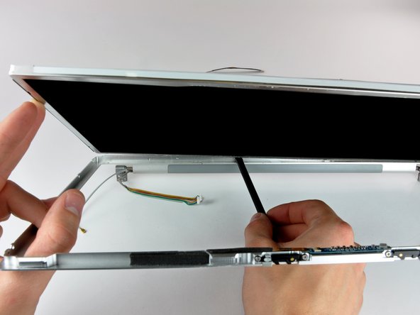
Grasp the display assembly on both sides and lift it up and out of the computer.
-
-
Cette étape n’est pas traduite. Aidez à la traduire
-
Remove the two 5 mm Phillips screws from the lower left and right corners of the display (two screws total).
-
-
Cette étape n’est pas traduite. Aidez à la traduire
-
Insert the flat end of a spudger perpendicular to the face of the display between the plastic strip attached to the rear bezel and the front bezel.
-
With the spudger still inserted, rotate it away from the display to separate the front and rear bezels.
-
Work along the left edge of the display until the rear bezel is evenly separated from the front bezel.
-
-
Cette étape n’est pas traduite. Aidez à la traduire
-
Insert the flat end of a spudger perpendicular to the face of the display between the plastic strip attached to the rear bezel and the front bezel.
-
With the spudger still inserted, rotate it away from the display to separate the front and rear bezels.
-
Work along the right edge of the display until the rear bezel is evenly separated from the front bezel.
-
-
Cette étape n’est pas traduite. Aidez à la traduire
-
Insert the flat end of a spudger between the front bezel and the plastic strip attached to the rear bezel near the screw holes at the bottom corners of the display.
-
Rotate your spudger toward the rear bezel to separate it from the front bezel.
-
If necessary, enlarge the gap between the lower edge of the rear bezel and the clutch cover until the two components are completely separated.
-
-
Cette étape n’est pas traduite. Aidez à la traduire
-
Lift the rear bezel by its bottom edge and rotate it away from the display assembly to separate the top edge.
-
Remove the rear display bezel from the display assembly.
-
-
Cette étape n’est pas traduite. Aidez à la traduire
-
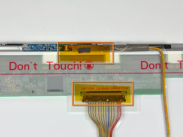
Remove the pieces of yellow kapton tape from the bottom left corner of the display.
-
Remove the pieces of tape securing the display data cable and camera cable to the display.
-
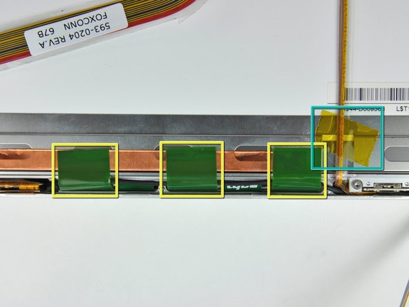
Peel the three green antenna ground straps off the copper tape along the bottom edge of the LCD.
-
Remove the piece of tape securing the camera cable to the LCD.
-
-
Cette étape n’est pas traduite. Aidez à la traduire
-
Carefully peel the camera cable off the foam tape along the top edge of the LCD.
-
-
Cette étape n’est pas traduite. Aidez à la traduire
-
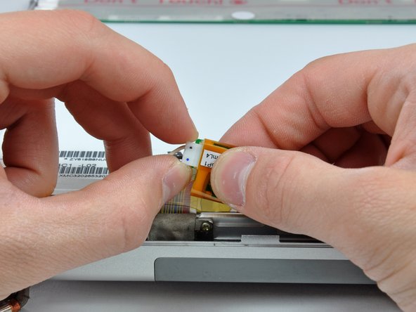
Use the tip of a spudger and carefully flip the ZIF connector bar up to release the before the camera cable.
-
Gently pull the camera cable away from its socket on the camera board.
-
-
Cette étape n’est pas traduite. Aidez à la traduire
-
Pull the display data cable connector away from its socket on the LCD.
-
-
Cette étape n’est pas traduite. Aidez à la traduire
-
Remove the four black Phillips screws along the left and right edges of the display (eight screws total).
-
-
Cette étape n’est pas traduite. Aidez à la traduire
-
Use the flat end of a spudger to gently lift one of the top corners of the LCD out of the front bezel.
-
-
Cette étape n’est pas traduite. Aidez à la traduire
-
Work your way along the top edge of the LCD, slowly prying the attached steel strip away from the front bezel.
-
-
Cette étape n’est pas traduite. Aidez à la traduire
-
Now that the top edge is free, slightly lift the LCD out of the front bezel for enough room to pry the steel strip along the lower edge of the LCD away from the front bezel.
-
Pry along the lower edge of the LCD until it is freed from the adhesive on the front bezel.
-
-
Cette étape n’est pas traduite. Aidez à la traduire
-
Lift the inverter out of the clutch cover.
-
Disconnect the LCD backlight connector from its socket on the inverter board.
-
-
Cette étape n’est pas traduite. Aidez à la traduire
-
Lift the LCD out of the front bezel, minding any cables that may get caught.
-


Annulation : je n'ai pas terminé ce tutoriel.
25 autres ont terminé cette réparation.

