Cette version peut contenir des modifications incorrectes. Passez au dernier aperçu vérifié.
Ce dont vous avez besoin
-
-
Boîtier fermé, placez l'Unibody à l'envers sur une surface plane.
-
Appuyez sur le côté rainuré du loquet de déverrouillage de la trappe d'accès de manière à saisir l'extrémité libre du loquet. Soulevez le loquet de déverrouillage à la verticale.
-
-
-
Tirez sur la languette en plastique blanc et retirez la batterie de votre MacBook Unibody.
-
-
-
Retirez les huit vis suivantes par lesquelles le boîtier inférieur est fixé au châssis :
-
Une vis Phillips 3 mm.
-
Trois vis Phillips 13,5 mm.
-
Quatre vis Phillips 3,5 mm.
-
-
Cette étape n’est pas traduite. Aidez à la traduire
-
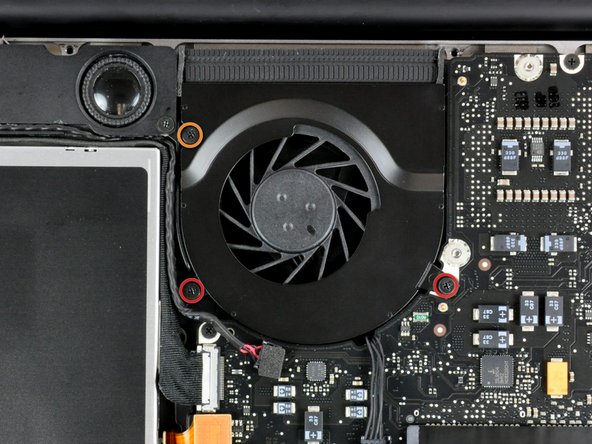
Remove the four 10.3 mm Phillips screws securing the mid wall to the upper case.
-
-
-
Avec une spatule (spudger), soulevez délicatement le connecteur du ventilateur pour le débrancher de la carte mère.
-
-
-
Cette étape n’est pas traduite. Aidez à la traduire
-
Each connector is different, so the following steps will show you how disconnect each in detail.
-
-
Cette étape n’est pas traduite. Aidez à la traduire
-
Remove the single Phillips screw securing the battery cable cover to the upper case.
-
Remove the battery cable cover from the upper case.
-
-
Cette étape n’est pas traduite. Aidez à la traduire
-
Use a spudger to pry the battery level indicator cable connector straight up off the logic board.
-
-
Cette étape n’est pas traduite. Aidez à la traduire
-
Disconnect the battery cable connector by pulling it straight away from the logic board.
-
-
Cette étape n’est pas traduite. Aidez à la traduire
-
Using the tip of a spudger, flip up the keyboard ribbon cable retaining flap.
-
Pull the keyboard ribbon cable straight out of its socket.
-
If the smaller connector at the right side of the keyboard ribbon cable is populated by another small black ribbon cable, remove it in a similar way to the above.
-
-
Cette étape n’est pas traduite. Aidez à la traduire
-
Use the flat end of a spudger to pry the trackpad connector straight up off the logic board.
-
-
Cette étape n’est pas traduite. Aidez à la traduire
-
Use the tip of a spudger to flip up the locking lever to release the IR sensor ribbon cable from its socket.
-
Use the tip of a spudger to pull the IR sensor ribbon cable straight away from the logic board.
-
-
Cette étape n’est pas traduite. Aidez à la traduire
-
Use the flat end of a spudger to pry the hard drive cable connector straight up off the logic board.
-
-
Cette étape n’est pas traduite. Aidez à la traduire
-
Use the flat end of a spudger to pry the optical drive cable connector straight up off the logic board.
-
-
Cette étape n’est pas traduite. Aidez à la traduire
-
Disconnect the display data cable by pulling the male end straight away from its socket.
-
-
Cette étape n’est pas traduite. Aidez à la traduire
-
Use the flat end of a spudger to pry the subwoofer cable connector straight up off the logic board.
-
-
Cette étape n’est pas traduite. Aidez à la traduire
-
Grab the plastic pull tab secured to the display data cable lock and rotate it toward the DC-in side of the computer.
-
Pull the display data cable connector straight away from its socket.
-
-
Cette étape n’est pas traduite. Aidez à la traduire
-
Remove the following two screws securing the display data cable bracket to the upper case:
-
One 7mm Phillips screw.
-
One 5mm Phillips screw.
-
Remove the two 7 mm Phillips screws from the DC-in board.
-
Lift the display data cable bracket out of the upper case.
-
-
Cette étape n’est pas traduite. Aidez à la traduire
-
If present, remove the two 4mm Phillips screws securing the bottom case clip to the upper case.
-
Lift the bottom case clip out of the upper case.
-
-
Cette étape n’est pas traduite. Aidez à la traduire
-
Remove the two 5mm Phillips screws securing the keyboard flex bracket to the upper case.
-
Lift the keyboard flex bracket out of the upper case.
-
-
Cette étape n’est pas traduite. Aidez à la traduire
-
Use the tip of a spudger to release the microphone from the upper case.
-
-
Cette étape n’est pas traduite. Aidez à la traduire
-
Remove the following five screws securing the logic board to the upper case:
-
Four 3mm Phillips screws.
-
One 3.5mm Phillips screw.
-
Lift the logic board from its left edge and pull it out of the upper case.
-


Annulation : je n'ai pas terminé ce tutoriel.
3 autres ont terminé cette réparation.
