Cette version peut contenir des modifications incorrectes. Passez au dernier aperçu vérifié.
Ce dont vous avez besoin
-
Cette étape n’est pas traduite. Aidez à la traduire
-
Insert eject pin to the small hole to open a gap.
-
Use guitar picks to cut the strong adhesive underneath this rear cover.
-
Remove back cover.
-
-
Cette étape n’est pas traduite. Aidez à la traduire
-
Use T3 Torx screwdriver to twist off all 21 screws.
-
Remove 2 protective rubbers securing the flashlight flex and battery flex connector.
-
-
Cette étape n’est pas traduite. Aidez à la traduire
-
Release the flashlight flex and battery flex connector.
-
-
Cette étape n’est pas traduite. Aidez à la traduire
-
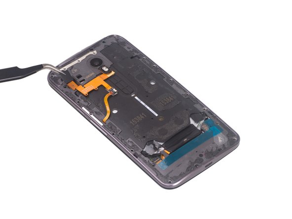
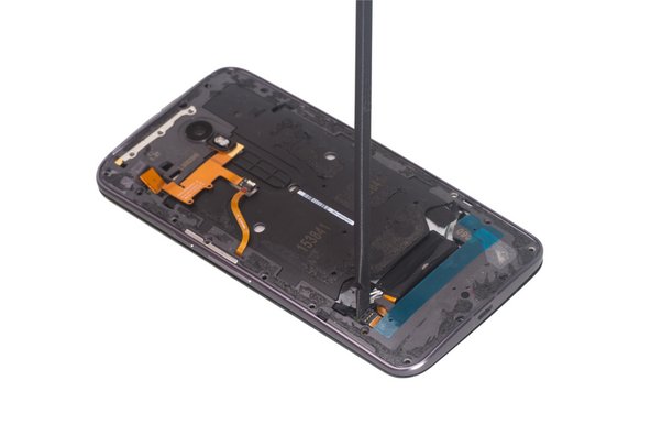
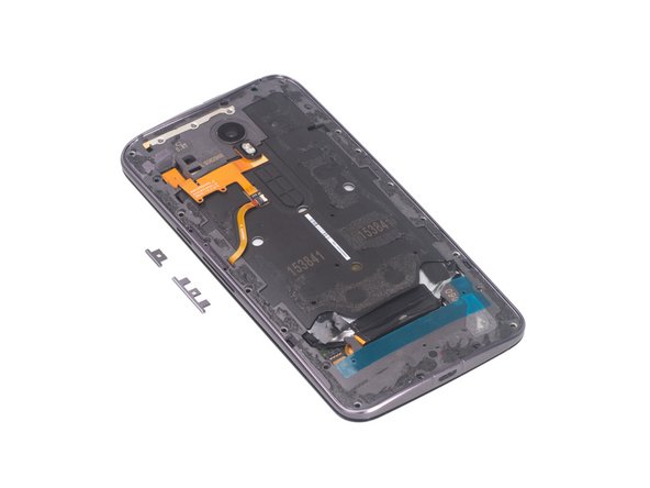
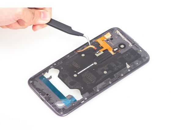
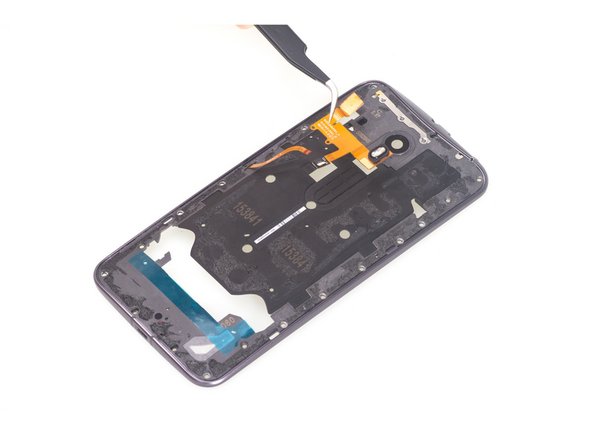
Remove metal bar securing side buttons, careful of the extremely tiny springs that provide pressure from the frame to the buttons, then be free to remove side buttons.
-
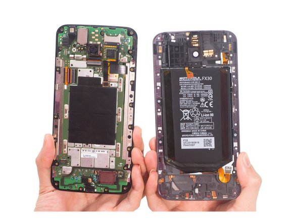
Remove middle frame bezel.
-
-
Cette étape n’est pas traduite. Aidez à la traduire
-
Pull out 2 battery sticker strips.
-
Loosen the NFC flex connector attached to the battery.
-
Pry up and remove battery.
-
-
-
Cette étape n’est pas traduite. Aidez à la traduire
-
There is no adhesive sticking headphone jack, just use tweezers to remove it.
-
Then peel off the NFC antenna.
-
-
Cette étape n’est pas traduite. Aidez à la traduire
-
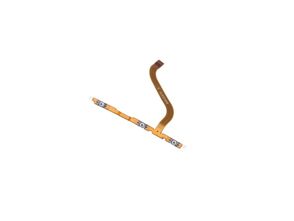
Release flashlight flex connector connecting side button flex.
-
Take away flashlight flex.
-
-
Cette étape n’est pas traduite. Aidez à la traduire
-
Twist off one Torx T3 screw securing motherboard.
-
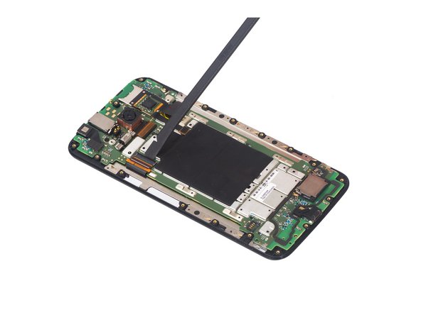
Release the LCD screen connector here.
-
-
Cette étape n’est pas traduite. Aidez à la traduire
-
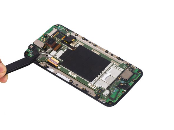
Release this connector.
-
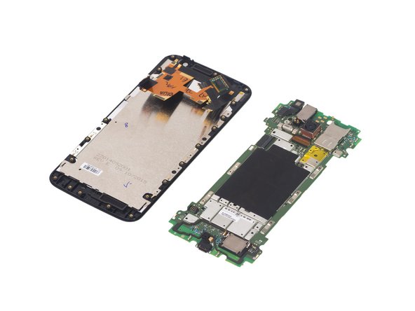
Separate motherboard assembly from LCD screen assembly.
-
-
Cette étape n’est pas traduite. Aidez à la traduire
-
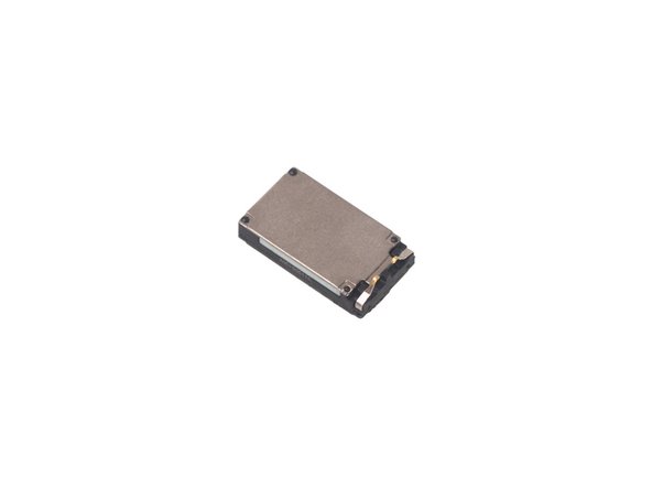
There is adhesive underneath. Pry up and then remove top speaker.
-
-
Cette étape n’est pas traduite. Aidez à la traduire
-
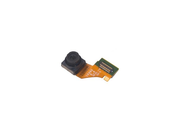
Peel off protective tape on the rear camera.
-
Release rear camera flex and then remove the camera.
-
-
Cette étape n’est pas traduite. Aidez à la traduire
-
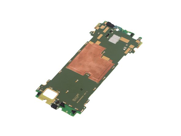
Pry up and remove loudspeaker.
-
Now it leaves the motherboard assembly with some parts like charing port and vibration motor.
-
-
Cette étape n’est pas traduite. Aidez à la traduire
-
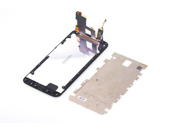
Remove the LCD shield easily.
-
Finally it leaves the LCD screen with digitizer and front housing.
-


Annulation : je n'ai pas terminé ce tutoriel.
36 autres ont terminé cette réparation.

78 commentaires
Can anybody help with how you replace the speaker grills? As it is not included in the replacement assembly screens?
I believe they are underneath the 'housing frame' which is the piece of plastic around the edge of the glass.
Hi just take them off with tweezers
Can anyone tell by looking at the board if the X Pure has a FM chip that is wired? Currently all anyone is saying on forums is that the phone isn't FM enabled (which could only mean it isn't turned on), not that is is missing the chip or that the chip hasn't been wired to allow the FM to be enabled.
Does anybody know what lengths the 21 screws are?