Ce dont vous avez besoin
-
Cette étape n’est pas traduite. Aidez à la traduire
-
The CitiZ is a compact coffee-making gizmo. Opening it requires a proprietary tool that Nespresso doesn't sell.
-
You can get into it with a pair of needle-nose pliers. The pliers I used aren't ideal — you want something that can get into the recessed slots.
-
-
Cette étape n’est pas traduite. Aidez à la traduire
-
There are six ovoid screws on the bottom case. The screws look like rivets, but they are actually oval.
-
You can painstakingly remove them with pliers. Take your time.
-
If you can't get pliers to work, other people have had success using superglue, melting a BIC pen into the shape of the screw, or machining a custom bit.
-
-
Cette étape n’est pas traduite. Aidez à la traduire
-
Now that the screws are removed, use a screwdriver or a spudger to pry the tabs holding the bottom case on.
-
The easiest place to get in is the power plug. Be careful not to nick it. (And make sure you're unplugged from the wall!)
-
-
Cette étape n’est pas traduite. Aidez à la traduire
-
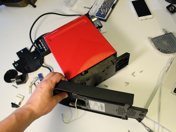
Carefully open the lower case and set the machine on its side.
-
-
Cette étape n’est pas traduite. Aidez à la traduire
-
The plastic strain relief bracket on the power cable is challenging to remove. Insert a small flathead screwdriver into the small slot on one side to disengage the tab.
-
-
Cette étape n’est pas traduite. Aidez à la traduire
-
Nespresso makes heavy use of spade connectors inside this machine.
-
Grab one side firmly with your pliers and pull on the other side of the connector with your fingers. Do not pull on the cable, because you can pull it free from the spade connector.
-
-
Cette étape n’est pas traduite. Aidez à la traduire
-
Disconnect the blue neutral wire.
-
Remove the power switch from the case.
-
-
Cette étape n’est pas traduite. Aidez à la traduire
-
Firmly grasp the power cable connectors and remove them from the power switch.
-
-
Cette étape n’est pas traduite. Aidez à la traduire
-
Insert the tip of a spudger into the silicon tube and slide it off the nipple.
-
-
Cette étape n’est pas traduite. Aidez à la traduire
-
Thread the remaining tubes and wires through the bottom case to free it from the main unit.
-
Remove the bottom case.
-
-
-
Cette étape n’est pas traduite. Aidez à la traduire
-
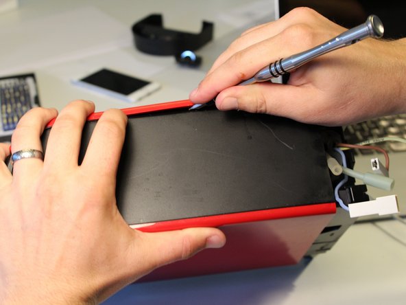
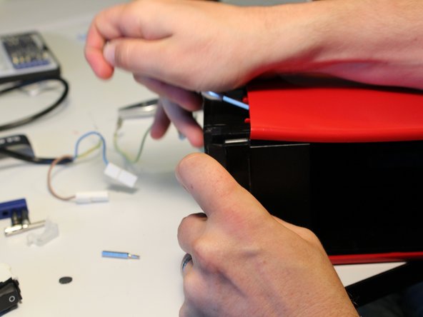
Removing the outer shell requires some force.
-
There are a series of tabs on all four sides of the shell.
-
Start by using a flathead screwdriver or spudger to pop the first tab.
-
Work your way around the case, freeing tabs as you go.
-
-
Cette étape n’est pas traduite. Aidez à la traduire
-
Extricate the control button wires from the case assembly.
-
-
Cette étape n’est pas traduite. Aidez à la traduire
-
Remove the blue tube from the flow meter.
-
Remove the sensor data cable.
-
-
Cette étape n’est pas traduite. Aidez à la traduire
-
The pump feed tube uses a clever retaining clip. Remove this clip with your pliers. It does not require much force.
-
Repeat this for the clip attaching the valve to the water heater.
-
-
Cette étape n’est pas traduite. Aidez à la traduire
-
Disconnect the power cable from the spade connector on the side of the water pump.
-
-
Cette étape n’est pas traduite. Aidez à la traduire
-
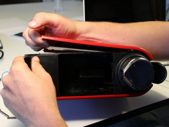
Remove the side panel from the other side of the unit. The tab positions are similar to the first side panel.
-
-
Cette étape n’est pas traduite. Aidez à la traduire
-
Disengage the tabs holding the top assembly to the case.
-
-
Cette étape n’est pas traduite. Aidez à la traduire
-
Remove the front spout.
-
Remove the top case. Be careful, the button cables are captive to the case. Disentangle the cables and set the top next to the frame.
-
-
Cette étape n’est pas traduite. Aidez à la traduire
-
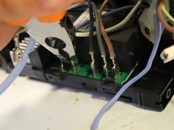
Power cables, from left to right: heat (white), neutral (blue), pump (dark grey), pump ground? (light grey), line (brown).
-
Disconnect each cable with your pliers.
-
-
Cette étape n’est pas traduite. Aidez à la traduire
-
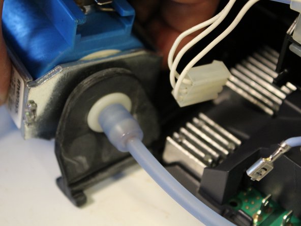
Slide the water pump out. The rubber vibration isolator doubles as a mounting bracket that neatly slides out from the plastic frame.
-
-
Cette étape n’est pas traduite. Aidez à la traduire
-
Remove the (rather over-engineered) silicon mounting bracket holding the coffee feed line in place.
-
-
Cette étape n’est pas traduite. Aidez à la traduire
-
Disconnect the latches and slide the heating assembly out of the frame.
-
-
Cette étape n’est pas traduite. Aidez à la traduire
-
Free the latch on the right side of the circuit board and then carefully lever it out.
-
Don't use too much force on the plastic bracket on top of the circuit board because there are two vulnerable capacitors on the rear left side of the board.
-
-
Cette étape n’est pas traduite. Aidez à la traduire
-
The BTB12 AC 12 Amp triac requires a large heat sink that is riveted onto the main board.
-


32 commentaires
or you can make your own tool! See http://www.maultech.com/chrislott/blog/2...
Where is the heating element then?
Hi Junaho.
Did you have a look to Step 26 ?
I see, my bad.