Cette version peut contenir des modifications incorrectes. Passez au dernier aperçu vérifié.
Ce dont vous avez besoin
-
Cette étape n’est pas traduite. Aidez à la traduire
-
With the lens facing forward, remove the one 4.2 mm screw on the bottom right hand corner of the camera.
-
-
Cette étape n’est pas traduite. Aidez à la traduire
-
Remove the chrome side cover from the body of the camera.
-
-
Cette étape n’est pas traduite. Aidez à la traduire
-
Remove the four 3.2 mm screws on the bottom of the camera.
-
-
Cette étape n’est pas traduite. Aidez à la traduire
-
Remove the two 3.2 mm screws from the right side of the camera (with lens is facing forward)
-
Remove the one 3.2 mm screw from the left side of the camera (with lens facing foward)
-
-
Cette étape n’est pas traduite. Aidez à la traduire
-
Gently separate the back cover from the body of the camera.
-
-
Cette étape n’est pas traduite. Aidez à la traduire
-
Use the tweezers to disconnect the ribbon from the circuit board.
-
-
-
Cette étape n’est pas traduite. Aidez à la traduire
-
Remove the one 2.6 mm screw from the left side of the camera (with the lens facing forward)
-
-
Cette étape n’est pas traduite. Aidez à la traduire
-
Gently separate the front cover from the body of the camera.
-
-
Cette étape n’est pas traduite. Aidez à la traduire
-
Remove the two 3.2 mm screws that hold the flash to the front cover.
-
-
Cette étape n’est pas traduite. Aidez à la traduire
-
Use the Spudger to remove the copper colored light bulb clip.
-
Remove the front cover entierly from the camera body.
-
-
Cette étape n’est pas traduite. Aidez à la traduire
-
From the top view of the camera, remove the one 5.8 mm screw.
-
From the top view of the camera, remove the one 2.8 mm screw
-
-
Cette étape n’est pas traduite. Aidez à la traduire
-
Remove the three 3.4 mm screws from the back side of the camera.
-
-
Cette étape n’est pas traduite. Aidez à la traduire
-
Remove the two 3.4 mm screws from the side of the camera.
-
-
Cette étape n’est pas traduite. Aidez à la traduire
-
Separate the two metal body pieces from the rest of the camera.
-
-
Cette étape n’est pas traduite. Aidez à la traduire
-
Gently remove the two ribbons connecting the lens to the mother board.
-
-
Cette étape n’est pas traduite. Aidez à la traduire
-
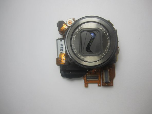
Gently separate the camera lens from the mother board.
-
-
Cette étape n’est pas traduite. Aidez à la traduire
-
The mother board is permanently fixed to the battery housing.
-


Annulation : je n'ai pas terminé ce tutoriel.
Une autre personne a terminé cette réparation.
Équipe

Cuesta, Team 1-6, Zipperian Fall 2011 Membre de l'équipe Cuesta, Team 1-6, Zipperian Fall 2011
CUESTA-ZIPPERIAN-F11S1G6
2 membres
6 tutoriels rédigés