Cette version peut contenir des modifications incorrectes. Passez au dernier aperçu vérifié.
Ce dont vous avez besoin
-
Cette étape n’est pas traduite. Aidez à la traduire
-
Remove the two visible 6.0 mm Philips #0 screws on the left and right sides of the viewfinder. These screws are highlighted in red.
-
-
Cette étape n’est pas traduite. Aidez à la traduire
-
Remove the four 6.0 mm Philips #0 screws on the left and right sides of the camera.
-
-
Cette étape n’est pas traduite. Aidez à la traduire
-
Remove the four highlighted 3.0 mm Philips #0 screws on the bottom of the camera.
-
-
-
Cette étape n’est pas traduite. Aidez à la traduire
-
While pulling the bottom down, remove the back of the camera.
-
-
Cette étape n’est pas traduite. Aidez à la traduire
-
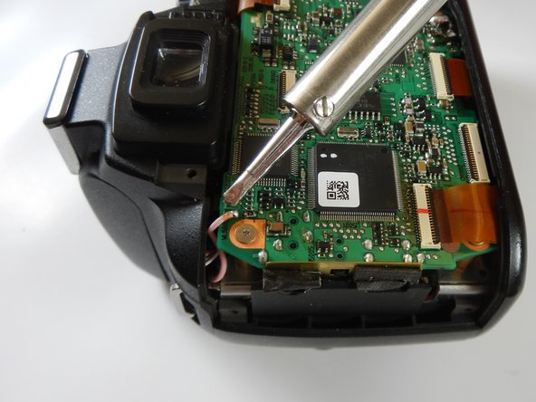
Remove the solder connecting the red wire to the mainboard.
-
-
Cette étape n’est pas traduite. Aidez à la traduire
-
Desolder the 4 smaller wires near the bottom of the mainboard.
-
-
Cette étape n’est pas traduite. Aidez à la traduire
-
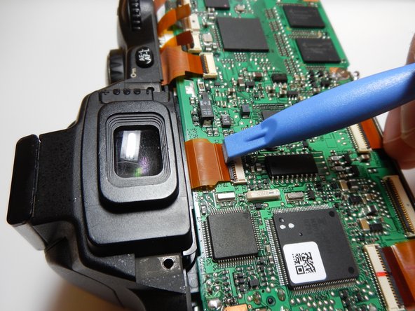
Use the plastic opening tool to release the ribbon cables attached to the mainboard.
-
-
Cette étape n’est pas traduite. Aidez à la traduire
-
Remove the five 3.0mm Philips #1 screws holding the mainboard down.
-
-
Cette étape n’est pas traduite. Aidez à la traduire
-
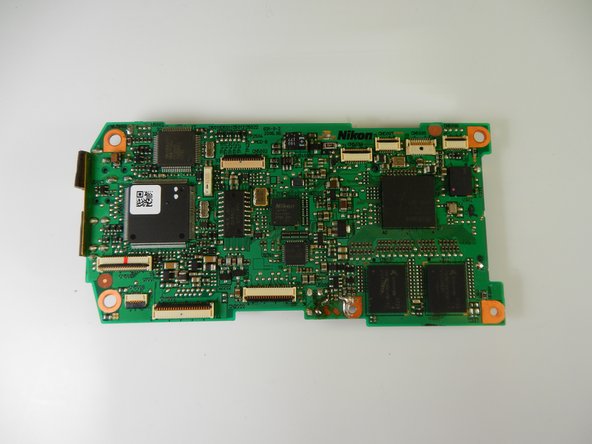
Lift the mainboard up to reveal the final connection.
-


Annulation : je n'ai pas terminé ce tutoriel.
5 autres ont terminé cette réparation.
Équipe

Cal Poly, Team 6-19, Maness Winter 2014 Membre de l'équipe Cal Poly, Team 6-19, Maness Winter 2014
CPSU-MANESS-W14S6G19
4 membres
7 tutoriels rédigés
Un commentaire
What is the ordering of the small wires on the bottom? It is hard to put back together from the photos. Thanks!