Cette version peut contenir des modifications incorrectes. Passez au dernier aperçu vérifié.
Ce dont vous avez besoin
-
Cette étape n’est pas traduite. Aidez à la traduire
-
Remove the two 4.8 mm Phillips screws securing the battery side of the rear cover to the D70.
-
-
Cette étape n’est pas traduite. Aidez à la traduire
-
Remove the two 4.8 mm Phillips screws securing the port side of the rear cover to the D70.
-
-
Cette étape n’est pas traduite. Aidez à la traduire
-
Use your fingernail to flip up the ZIF locking flap on the LCD ribbon cable socket.
-
Pull the LCD board ribbon cable out of its socket.
-
-
Cette étape n’est pas traduite. Aidez à la traduire
-
Carefully pull the sides of the rear cover away from the body of the D70.
-
-
-
Cette étape n’est pas traduite. Aidez à la traduire
-
Pull the rear cover off the body of the D70, minding the LCD board ribbon cable that may get caught.
-
-
Cette étape n’est pas traduite. Aidez à la traduire
-
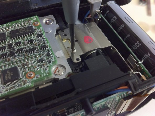
Remove the two Phillips screws securing the holder of the CF Card Slot.
-
-
Cette étape n’est pas traduite. Aidez à la traduire
-
Use Tweezers to open the locking on the ribbon cable socket.
-
-
Cette étape n’est pas traduite. Aidez à la traduire
-
Carefully fold the Pull the ribbon cable towards the CF Slot
-
-
Cette étape n’est pas traduite. Aidez à la traduire
-
Remove the two Phillips screws to separate the Holder from the Slot.
-


Annulation : je n'ai pas terminé ce tutoriel.
24 autres ont terminé cette réparation.

6 commentaires
How do i change out the board with the pins…… second hand cam someone bent alot of pins
I can order board or can i order the whole cf ?
You can find them on ebay real easy. both full assemblies and just the board with the pins