Cette version peut contenir des modifications incorrectes. Passez au dernier aperçu vérifié.
Ce dont vous avez besoin
-
-
Dévissez les deux vis cruciformes Phillips fixant le cache de la batterie au boîtier inférieur.
-
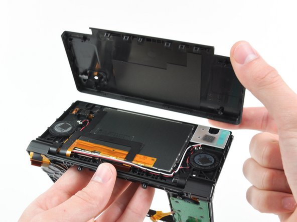
Saisissez le cache de la batterie et enlevez-le du boîtier inférieur.
-
-
-
Deux vis sont cachées sous les deux pieds en caoutchouc marqués en rouge sur la photo.
-
Avec la pointe d'une spatule (spudger), faites levier pour retirer les pieds en caoutchouc du boîtier inférieur.
-
-
-
Insérez la spatule (spudger) entre le boîtier inférieur et le panneau inférieur à côté du coin supérieur droit de la DSi.
-
Parcourez soigneusement avec la spatule le bord du boîtier inférieur. Vous ouvrez ainsi une fente entre le boîtier et le reste de la DSi.
-
Continuez à parcourir avec la spatule le pourtour de la DSi jusqu'à avoir séparé la plus grande partie du boîtier inférieur.
-
-
-
Soulevez doucement le boîtier inférieur par son bord inférieur.
-
Utilisez l'extrémité plate d'un tournevis pour faire levier et enlevez la nappe du volume et de la carte SD de son emplacement sur la carte mère.
-
Une fois que la nappe (dans l'encadré orange) est complètement enlevée, vous pouvez retirer tout le boîtier inférieur.
-
-
-
Retirez la carte Wi-Fi de la carte mère en la saisissant du côté le plus proche de la prise Jack.
-
-
-
Utilisez la pointe d'une spatule (spudger) pour soulever le connecteur de la carte alimentation hors de sa prise sur la carte mère.
-
-
-
Avec votre ongle ou un outil en plastique, ouvrez le clapet de retenue des trois prises ZIF suivantes:
-
La nappe du tactile inférieur
-
La nappe de l'écran inférieur
-
La nappe de la carte alimentation
-
Après avoir ouvert les clapets de retenue des trois prises, utilisez vos doigts ou des pincettes pour tirer doucement les nappes hors de leurs prises.
-
-
-
-
Soulevez légèrement la carte mère vers le haut, ce qui laissera voir la nappe de l'écran supérieur au-dessus des boutons ABXY.
-
Utilisez votre ongle ou un outil en plastique pour ouvrir soigneusement le clapet de retenue de la nappe de l'écran supérieur.
-
Retirez la carte mère de la DSi.
-
-
-
Utilisez la pointe d'une spatule (spudger) pour extraire du cadre de la DSi la protection métallique de l'écran LCD inférieur.
-
Soulevez l'ensemble LCD inférieur hors de la DSi.
-
-
Cette étape n’est pas traduite. Aidez à la traduire
-
Use a pushpin to remove the four plastic screw covers on the front bezel.
-
-
Cette étape n’est pas traduite. Aidez à la traduire
-
Remove the four Phillips screws securing the rear bezel to the front bezel.
-
-
Cette étape n’est pas traduite. Aidez à la traduire
-
Using two hands, gently slide the rear bezel upwards.
-
Slightly close the case of the DSi and lift the rear bezel straight up out of the DSi.
-
-
Cette étape n’est pas traduite. Aidez à la traduire
-
Continue de-routing the microphone and Wi-Fi antenna cables through the opening located on the bottom DSi's framework.
-
-
Cette étape n’est pas traduite. Aidez à la traduire
-
Remove the five Phillips screws securing the power board to the DSi's framework.
-
Lift and remove the power board from the DSi.
-
-
Cette étape n’est pas traduite. Aidez à la traduire
-
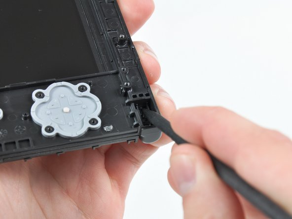
Push the metal hinge pin inward on the D-pad side of the front lower panel with the tip of a spudger.
-
The pin should move about 3 mm and stop. It is not necessary to try to completely remove the pin.
-
-
Cette étape n’est pas traduite. Aidez à la traduire
-
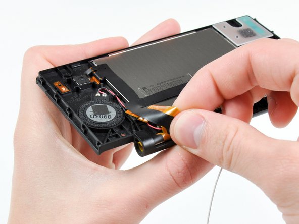
Slightly detach the lower and upper halves of the DSi.
-
De-route the upper LCD and dual camera ribbon cables through the slit near the ABXY side of the front lower panel.
-
Separate the lower and upper halves from each other.
-
-
Cette étape n’est pas traduite. Aidez à la traduire
-
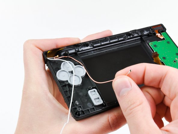
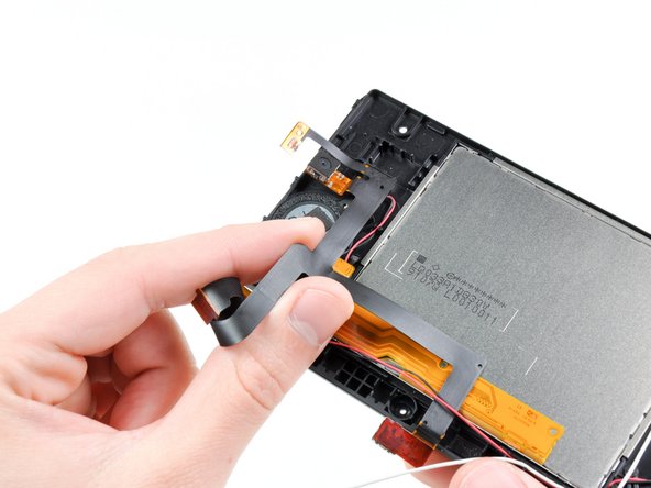
Using your fingers, grasp the microphone cable and de-route it through the hinge.
-
The microphone will likely pop out of its housing, so it is probably easier to completely remove it at this point.
-
De-route the Wi-Fi cable through the hinge.
-
-
Cette étape n’est pas traduite. Aidez à la traduire
-
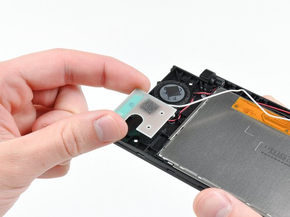
Tightly coil the display and dual camera ribbon cables enough to push them through the steel hinge tube.
-
Remove the steel hinge tube.
-
Carefully push both coiled ribbon cables through the tube molded into the front upper panel.
-
-
Cette étape n’est pas traduite. Aidez à la traduire
-
Pry the front-facing camera straight up out of its housing in the front bezel.
-
-
Cette étape n’est pas traduite. Aidez à la traduire
-
Lift the rear-facing camera out of its housing in the front bezel.
-
Remove the dual camera cable assembly from the DSi.
-
-
Cette étape n’est pas traduite. Aidez à la traduire
-
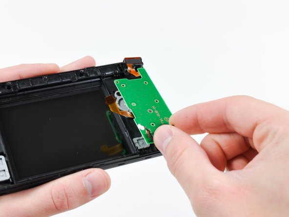
De-route the Wi-Fi antenna cable from its channel in the front bezel.
-
Lift the Wi-Fi antenna board straight up and remove it from the DSi.
-
-
Cette étape n’est pas traduite. Aidez à la traduire
-
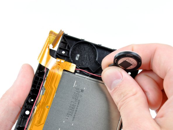
Use the flat end of a spudger to pry the right speaker straight up and out of its housing in the front upper panel.
-
Lift the right speaker and set it on top of the upper LCD.
-
-
Cette étape n’est pas traduite. Aidez à la traduire
-
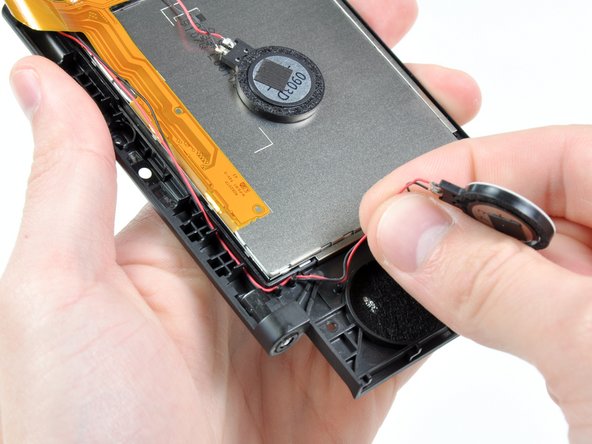
In the same manner as previously described, remove the left speaker.
-
De-route the left speaker cables from underneath the upper LCD.
-
Lay the left speaker on top of the upper LCD.
-
-
Cette étape n’est pas traduite. Aidez à la traduire
-
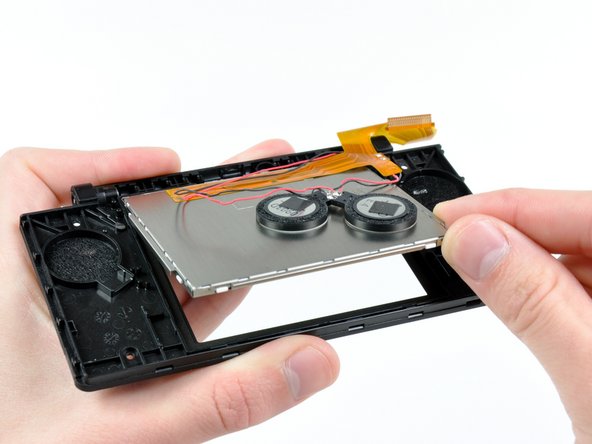
Cautiously wedge the flat end of spudger underneath the upper LCD.
-
Loosen the adhesive by running the spudger along the perimeter of the upper LCD.
-
Lift the upper LCD by its upper right corner and remove it from the front upper panel.
-
-
Cette étape n’est pas traduite. Aidez à la traduire
-
Desolder the speakers from the upper LCD by heating up the solder joints with a soldering iron and simultaneously using a pair of tweezers to pull the speaker wires away from the logic board.
-


Annulation : je n'ai pas terminé ce tutoriel.
30 autres ont terminé cette réparation.

12 commentaires
The tricky part is getting the upper screen and black ribbon through the hinge. I found that curling them and pushing them through a drinking straw that was cut short first and then pushing the straw through the hinge hole made it a whole lot easier.
So true. I just broke my second ribbon cable while replacing the case. While most repairs on the dsi are relatively easy, this ribbon cable makes any repairs that involve it a nightmare.
I curled the larger (new) cable the same way the smaller one was already curled. Just spend some time doing that until it was shaped that way and it was a lot easier to get both through the molded tube and ring.
Tplan -
While doing this I accident messed something up. When I power on the DSi, the bottom screen just flashes and the DS turns off. What did I do wrong?