Cette version peut contenir des modifications incorrectes. Passez au dernier aperçu vérifié.
Ce dont vous avez besoin
-
Cette étape n’est pas traduite. Aidez à la traduire
-
Remove six 13.25mm Phillips screws on the bottom of the system.
-
Once all screws are removed, simply lift the bottom half away from the top housing.
-
-
Cette étape n’est pas traduite. Aidez à la traduire
-
Remove seven 13.25mm Phillips screws around the perimeter of the RF shield.
-
Lift the RF shield up and away from the system and place aside.
-
-
Cette étape n’est pas traduite. Aidez à la traduire
-
Remove four 13.25mm Phillips screws from the four corners of the cartridge tray.
-
Remove two 17.25mm Phillips screws from the top of cartridge tray.
-
Once free, slide the cartridge tray towards you and then lift slightly in the front to remove.
-
-
Cette étape n’est pas traduite. Aidez à la traduire
-
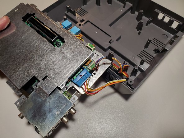
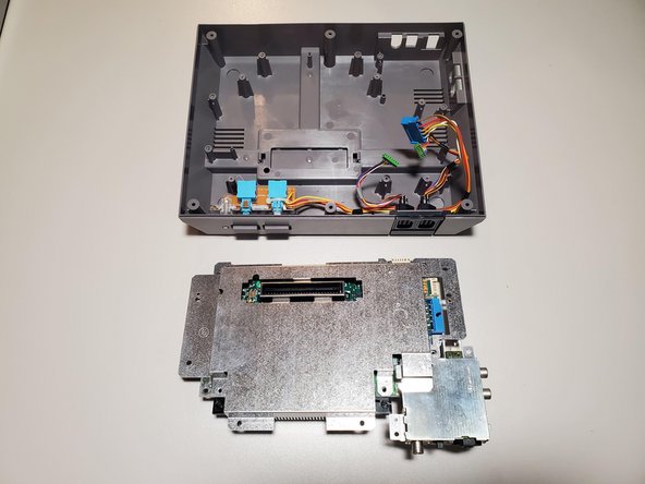
Remove three 13.25mm Phillips screws to free the motherboard from the bottom housing.
-
Carefully lift the motherboard and turn it over to find the wired connections.
-
-
-
Cette étape n’est pas traduite. Aidez à la traduire
-
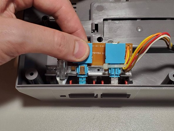
Disconnect the wired connections from the motherboard.
-
Player 1 (Shorter wires)
-
Player 2 (Longer wires)
-
Power/Reset Buttons
-
-
Cette étape n’est pas traduite. Aidez à la traduire
-
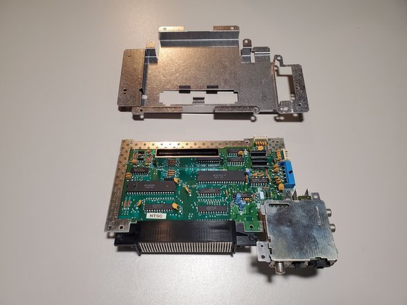
The bottom RF shield is held on by tension around the expansion port. Lift the shield up and away from the motherboard.
-
-
Cette étape n’est pas traduite. Aidez à la traduire
-
To remove the 72-Pin connector, apply force to each edge and slide the connector off the contacts on the motherboard.
-
-
Cette étape n’est pas traduite. Aidez à la traduire
-
Remove two 13.25mm Phillips screws from the button assembly. Lift slightly in the back and then up and away from the housing to remove.
-
-
Cette étape n’est pas traduite. Aidez à la traduire
-
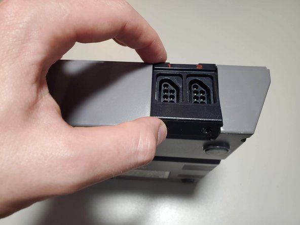
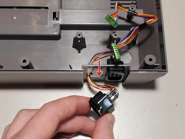
Remove two 7.25mm Phillips screws from the bottom of the system. Lift the controller port faceplate up and away.
-
Remove the controller ports by feeding them through the port holes to the front of the housing.
-
-
Cette étape n’est pas traduite. Aidez à la traduire
-
Remove seven 7.25mm small flathead screws from the inside of the top housing.
-
Two of these screws also hold a spring for the door. When reassembling, refer to the keyed shape of the plastic to orient these correctly.
-
-
Cette étape n’est pas traduite. Aidez à la traduire
-
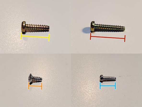
Screw List
-
(19x) 13.25mm Phillips
-
(2x) 17.25mm Phillips
-
(2x) 7.25mm Phillips (Silver, large cap)
-
(7x) 7.25mm Flathead (Silver, small)
-


Annulation : je n'ai pas terminé ce tutoriel.
14 autres ont terminé cette réparation.
