Cette version peut contenir des modifications incorrectes. Passez au dernier aperçu vérifié.
Ce dont vous avez besoin
-
Cette étape n’est pas traduite. Aidez à la traduire
-
Use a plastic opening tool to carefully pry off the four rubber feet from the control box.
-
You have now revealed the four 9 mm Phillips #1 screws underneath the rubber feet.
-
-
Cette étape n’est pas traduite. Aidez à la traduire
-
Use a Phillips #1 Screwdriver to unscrew the four 9mm Phillips screws on the bottom of the control box.
-
You can now remove the bottom lid of the control box. It should come apart easily.
-
-
Cette étape n’est pas traduite. Aidez à la traduire
-
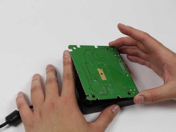
Use your finger(s) to start lifting the motherboard from the control box casing. While doing so, use your other hand to push the DVI connector into the control box casing.
-
When the DVI connector has cleared the casing, lift the motherboard.
-
-
-
Cette étape n’est pas traduite. Aidez à la traduire
-
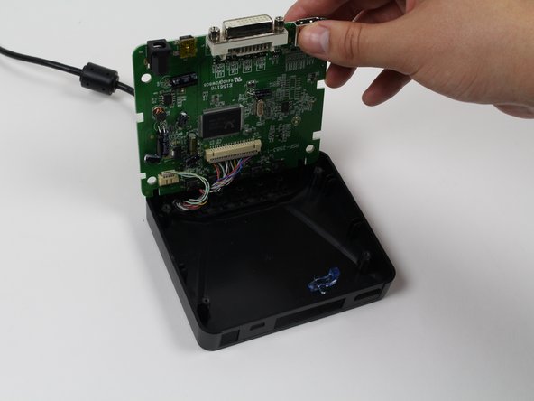
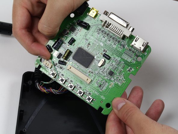
Use a plastic opening tool or your fingernails to disconnect the grey wire connectors. To make removal easier, pry the left and right edges to carefully remove the connector.
-
Do so for both of the wires attached to the motherboard.
-
Now fully separate the motherboard from the control box casing.
-
-
Cette étape n’est pas traduite. Aidez à la traduire
-
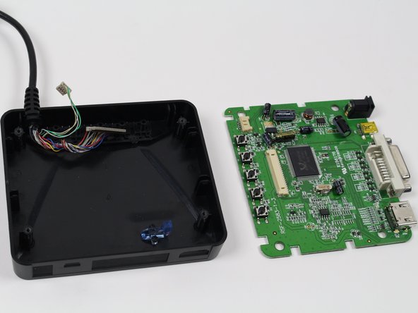
You now have the motherboard separated from the control box.
-
Identify the buttons that are not working.
-
-
Cette étape n’est pas traduite. Aidez à la traduire
-
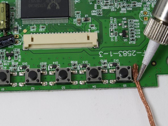
For each button that needs to be replaced, use a soldering iron and soldering braid to desolder the four metal points.
-
-
Cette étape n’est pas traduite. Aidez à la traduire
-
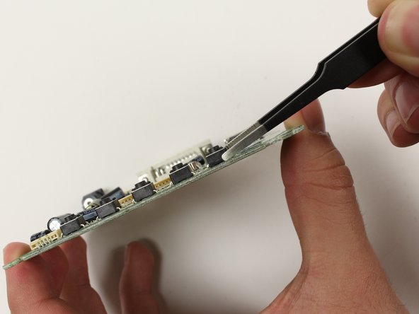
Now that each button with issues is desoldered, use tweezers to grab each button and detach from the motherboard.
-
If the button does not come off easily, go back to the previous step and ensure each of the four metal points are properly desoldered.
-


Équipe

Cal Poly, Team 70-5, Forte Winter 2015 Membre de l'équipe Cal Poly, Team 70-5, Forte Winter 2015
CPSU-FORTE-W15S70G5
4 membres
6 tutoriels rédigés