Introduction
Step-by-step Instructions Guide
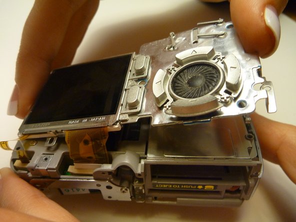
Olympus D590 Camera LCD Screen Replacement
Ce dont vous avez besoin
-
-
-
Using a Phillips #00 screwdriver, remove three screws fastened to the camera backplate edge.
-
-
-
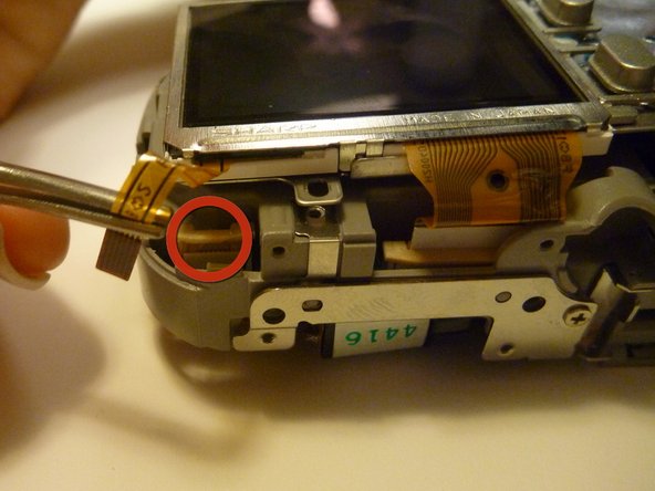
Remove one screw Phillips #00 from the right side of the LCD screen camera internal housing component.
-


Presque terminé !
To reassemble your device, follow these instructions in reverse order.
Conclusion
To reassemble your device, follow these instructions in reverse order.
Équipe

Cal Poly, Team 28-23, Regan Spring 2010 Membre de l'équipe Cal Poly, Team 28-23, Regan Spring 2010
CPSU-REGAN-S10S28G23
4 membres
14 tutoriels rédigés