Introduction
Follow this guide to remove and replace the motherboard for the OnePlus 5. The hardest part of the guide is getting the frame clips of the back cover free.
Ce dont vous avez besoin
-
-
Insert a SIM card eject tool, bit, or a straightened paperclip into the small hole below the SIM card tray, located near the rear cameras on the edge of the phone.
-
Press firmly to eject the tray.
-
-
-
Remove the two 2.6 mm T2 screws straddling the USB-C port on the bottom edge of the phone.
What are the reference of the screws ? They are missing in the one I bought !
Hi Yôken,
They help hold the back cover on. Most of the time, the clips are enough to hold the phone together.
Just FYI, for whatever reason my brand new OnePlus 5 had 0,8 mm stars screws instead of T2 Torx.
Definitely T2 for me. Do watch out during assembly. I have a feeling that it’s easy to strip these.
T2 for me too. It was missing in my kit and iFixit sent it later when I asked them about it.
-
-
-
Display panel seam: This seam is part of the display assembly. Do not pry at this seam, or you will separate and damage the display panel.
-
Frame seam: This is where the plastic frame meets the back cover. Only pry at this seam.
-
There are twelve clips that hold the frame against the rear case. Be aware of their location as you pry the back cover off in the following steps.
-
-
-
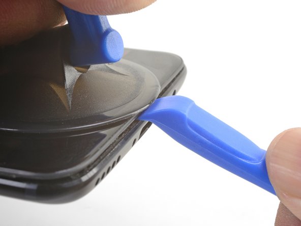
Place a suction cup near the bottom edge of the display.
-
Pull on the suction cup with strong steady force.
-
Press the edge of an opening tool straight into the frame seam near the suction cup until the edge wedges between the plastic frame and the back cover's lip.
I found the suction cup to be more of a hindrance and kept hitting the power button, making it necessary to stop and turn the phone off again. I watched a youtube video where the person didn't use a suction cup at all and decided to try that. I also found that a guitar pick type spudger worked far better than the one shown in the picture. If you're having trouble getting it started, I suggest trying those two things.
-
-
-
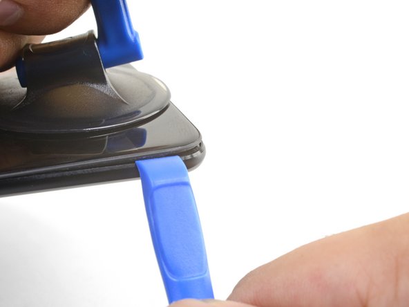
Once the opening tool's edge is wedged in position, carefully slide the tool along the bottom edge of the phone.
-
Carefully guide the opening tool around the left corner of the phone while keeping the tool's edge within the seam.
This was extremely difficult & took a lot of force. I needed a thin flat metal spudger and wrecked a couple of plastic ones in the process. I left a few scratches along the join in the process. It would be easier if I had something to hold the phone, in my hand I kept turning it on by accident.
what was the metal spudger did you use? I am having trouble as well. I cannot seem to pry the back cover and it feels like it is shut tightly, there are no crevices I can pry into. What was your strategy may I ask?
At first, I slightly opened the body with a plastic tool, but it was not enough to actually open the back cover. Then I used a thin metal screwdriver for this. It was difficult but nothing special. Just be sure that you are opening the correct seam between the body and the screen and don’t make sudden moves. I bent nothing, everything came back in place when reassembled.
ivan -
Same as David here: the plastic opening tools/guitar picks were doing nothing (not even creating the first "crack") . In the end I managed to open it using Jimmy (the metal knife/spudger), but not without scratching the whole metal cover.
-
-
-
Continue sliding the opening tool along the long edge, releasing the clips along the way.
-
-
-
With the bottom and left edge of the phone freed, gently wiggle the frame to release the top and right edge clips.
-
Align the top edge of the frame to the back cover and ensure that the top clips slip into place.
-
Squeeze along the long edges of the phone to snap the remaining clips into place.
Reinstalling the back cover stumped me for a second… If you’re struggling with aligning the top edge of the frame, remember that the camera is going to look off/pointed a bit too low until you actually clip the frame back in.
Really stupid but it was the only thing that tripped me up in this guide.
-
-
-
-
Use the point of a spudger to pry up and disconnect the back cover flex cable from its socket.
If the flex cable pins are damaged, the flex cable can be replaced.
If the connecter pins (on the motherboard) are damaged, you might need to do microsoldering (or contact a microsoldering company) to replace the damaged connector.
Brendan -
-
-
-
Use the point of a spudger to pry up and disconnect the battery connector from its socket.
-
-
-
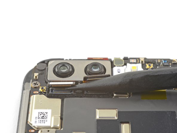
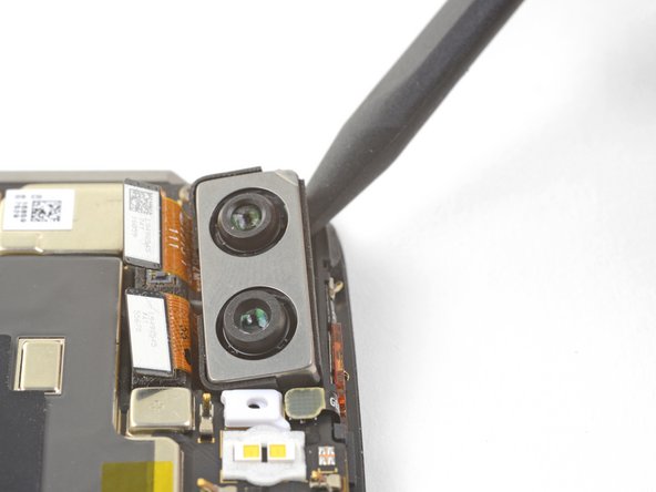
Use the point of a spudger to pry up and disconnect the two rear-facing camera connectors from their sockets on the motherboard.
-
-
-
Remove the rear-facing camera module.
-
-
-
Remove the six 2.6 mm Phillips screws securing the loudspeaker to the frame.
-
-
-
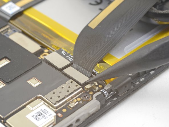
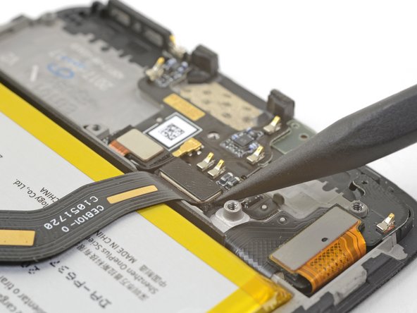
Use the point of a spudger to pry up and disconnect the interconnect flex cable from the socket.
This step is used in multiple guides, and not all of them require the cable to be bent away. You can just leave it sitting there, disconnected.
This image seems to show the daughterboard removed but there is no corresponding previous step. I see no way to remove the interconnect flex cable without removing the daughterboard. Possibly the volume switch can be removed with the cable still connected but I'm not confident enough to try this so will remove the daughterboard.
David,
Thanks for bringing this up. That's indeed a procedural error! I've added the missing steps in the affected guides.
-
-
-
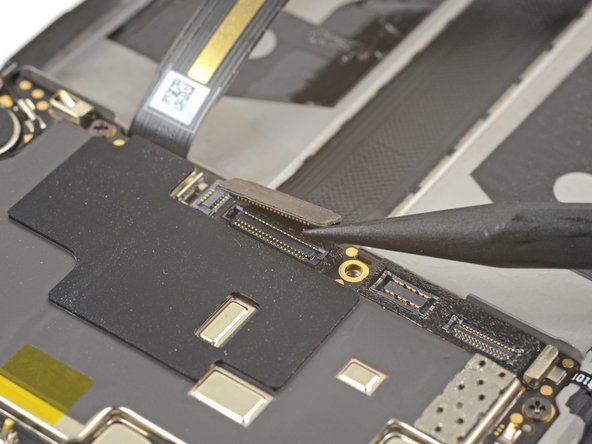
Use the point of a spudger to pry up and disconnect the display interconnect cable from its socket near the bottom edge of the motherboard.
Hallo, hier scheint der Schritt zu fehlen, in dem das Kameramodul entfernt wird.
Hello Norman,
You do not need to remove the camera module for procedure.
Hi Arthur,
You do need to remove the camera module, it’s in the photographs above, but not from step 33 onwards. It needs removing in order to remove the motherboard in steps 34 and 35.
Hi Alex! Thanks for the feedback! Can you relay which replacement guide you found the missing steps in? That would help me very much!
There are no steps 33, 34, 35 in this guide so the above comments must be from some other guide. With this phone I just lifted out the motherboard, carrying the camera with it. It went back the same way - but be careful not to trap the connector cable at the front under it.
-
-
-
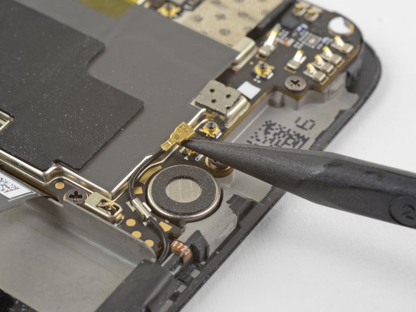
Slide the point of a spudger underneath the antenna interconnect cable that is connected to the motherboard above the vibration motor.
-
Pry up to disconnect the cable from its socket.
-
De-route the cable out of its motherboard grounding clip and move it out of the way.
Be attentive when reassembling if your unit doesn’t have a tape, which keeps antenna interconnect cable in place — I’ve accidentally got it squeezed with back cover.
-
-
-
Slide the point of a spudger under the small square antenna connector connected to the motherboard near the top edge.
-
Pry up to disconnect the antenna connector from its socket.
camera step seem to be missing
The cameras should be removed in step 14.
-
-
-
Use your fingers to lift up the top edge of the motherboard.
-
Lift the motherboard out of its recess and remove it.
The previous steps have not removed the camera although the pictures show it has been removed. I found that I could carefully lift away the motherboard with the camera attached.
When replacing the motherboard take care not to trap the small square antenna connector under the top edge.
-


To reassemble your device, follow these instructions in reverse order.
Take your e-waste to an R2 or e-Stewards certified recycler.
Repair didn’t go as planned? Check out our OnePlus 5 Answers Community for troubleshooting help.
To reassemble your device, follow these instructions in reverse order.
Take your e-waste to an R2 or e-Stewards certified recycler.
Repair didn’t go as planned? Check out our OnePlus 5 Answers Community for troubleshooting help.
Annulation : je n'ai pas terminé ce tutoriel.
5 autres ont terminé cette réparation.

