Cette version peut contenir des modifications incorrectes. Passez au dernier aperçu vérifié.
Ce dont vous avez besoin
-
Cette étape n’est pas traduite. Aidez à la traduire
-
Move the switch on the battery door to the Open position.
-
-
Cette étape n’est pas traduite. Aidez à la traduire
-
Push the small gray tab on the top right corner to the left. The battery will pop out slightly.
-
Keep your finger clear of the battery when it pops out.
-
-
Cette étape n’est pas traduite. Aidez à la traduire
-
Push the memory card in and let go.
-
Pull out the memory card.
-
-
Cette étape n’est pas traduite. Aidez à la traduire
-
Unscrew the small screws on the sides of the camera.
-
-
Cette étape n’est pas traduite. Aidez à la traduire
-
Unscrew the three small screws on the bottom(#00P, 3.3mm).
-
-
-
Cette étape n’est pas traduite. Aidez à la traduire
-
Lift up the bottom back cover by prying the bottom edge with the spudger.
-
Gently lift up the back cover with your hand from the bottom to the top.
-
-
Cette étape n’est pas traduite. Aidez à la traduire
-
Lift the tabs on the ZIF connectors.
-
The ribbon cables should easily come out of the ZIF connectors.
-
-
Cette étape n’est pas traduite. Aidez à la traduire
-
Using the spudger, pry off the top cover by gliding the spudger along the entire edge between the top cover and the front cover.
-
-
Cette étape n’est pas traduite. Aidez à la traduire
-
Remove the small screw in the hole towards the top of the camera(#00P, 5.4mm).
-
-
Cette étape n’est pas traduite. Aidez à la traduire
-
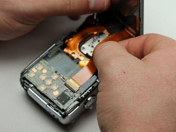
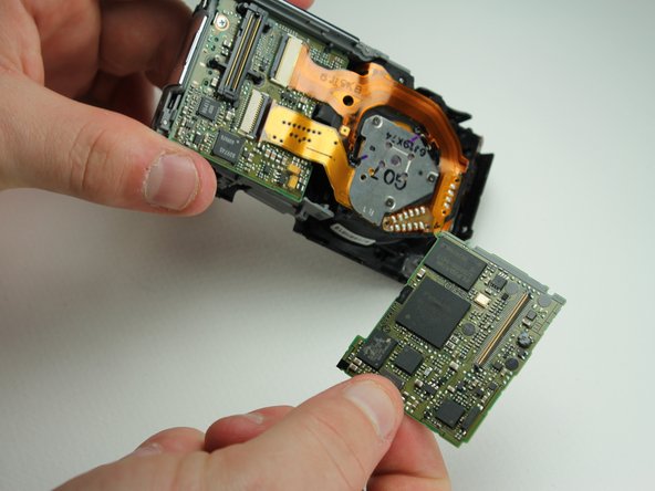
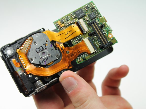
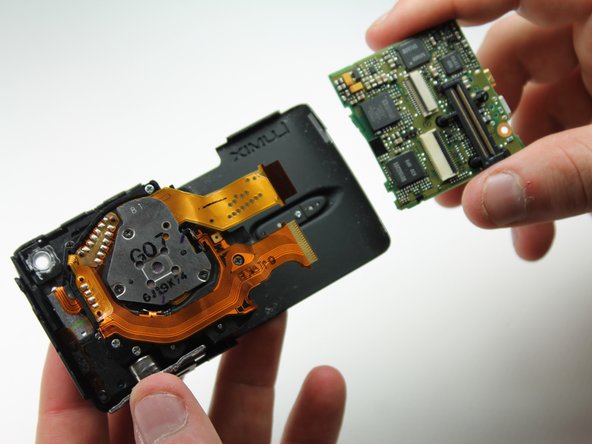
Use the spudger to lift up the back logic board.
-
Using your fingers, gently wiggle and pull off the back motherboard.
-
-
Cette étape n’est pas traduite. Aidez à la traduire
-
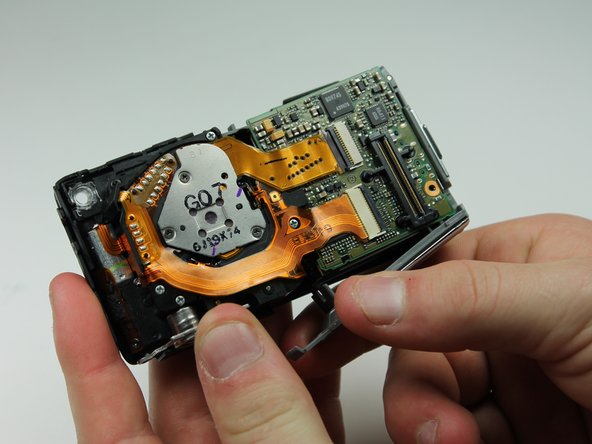
Remove the small screw holding down the lower motherboard(#00P, 3.2mm).
-
-
Cette étape n’est pas traduite. Aidez à la traduire
-
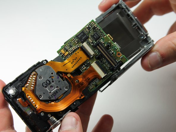
Use the spudger to lift the upper tab from the main housing.
-
Gently lift the lower tab from the main body by prying it with your finger.
-
Gently pull off the plastic motherboard housing sideways.
-
-
Cette étape n’est pas traduite. Aidez à la traduire
-
Gently lift the tabs on the ZIF connectors connecting the lens to the front motherboard.
-


Équipe

Cal Poly, Team 6-23, Amido Spring 2012 Membre de l'équipe Cal Poly, Team 6-23, Amido Spring 2012
CPSU-AMIDO-S12S6G23
4 membres
10 tutoriels rédigés