Introduction
Ce réveil est assez compliqué à ouvrir.
L'objectif était d'installer une antenne jack (BNC) pour attacher une antenne télescopique.
Ce dont vous avez besoin
-
-
il y a une vis sous l'étiquette brillante. Retirez l'étiquette et dévissez la vis pour retirer le panneau du fond.
-
Il y a deux languettes qui maintiennent le panneau en position horloge/lumière, donc vous devrez peut-être le faire bouger par devant pour pouvoir le retirer.
-
-
-
Retourner le réveil découvrira une petite section du support que l'on peut détacher en faisant levier dessus, vers le haut. C'est une petite pièce de plastique avec des crochets qu'il faudra désengager pour pouvoir la retirer.
Getting this section off/out without damaging it is nearly impossible. It’s hooked under the rear rim and it is held down by three clips. I ended up cutting the little bows that connect it to the back and then used pliers on one side to, well, basically break it out…
This stage was tricky but by poking a small flat-head screwdriver in alongside the tabs shown in the photo and twisting, I was able to remove it in one piece. Careful studying of of the image above shows where you need to go. Thanks for this excellent guide, I would never have figured this out without it.
Use a plastic tool or a something like a credit card to get that part out: it won’t break it and it is actually quite easy to remove (same tool used for smartphone)
Wow, this would have been impossible to do without seeing the pic of the part! I managed to get it free using a tiny flat-head screwdriver to the clip (all three, one by one) and a larger one pushing up on the rim simultaneously.
Thanks also from my side, it would have been an impossible mission without your guide and excellent illustrations. I also succeeded to remove the plastic strip lock with a tiny flat-head screwdriver and a pair of good steel pliers. No damage.
My model had a screw instead of the clips and was easy to remove. I did use a plastic pryer and think that helped.
-
-
-
-
Nous pouvons enfin dévisser deux vis Philips de plus pour retirer l'anneau des boutons.
Lift one end of the ring, tilting it toward the back of the alarm clock. That will get the bows out from under the rear rim so you can start removing it..
-
-
-
Il faut maintenant retirer les vis qui maintiennent la protection de l'écran frontal pour pouvoir l'enlever en tirant dessus vers l'avant.
-
Dévissez les quatre vis qui maintiennent l'assemblage de l'écran interne en place.
-
-
-
L'assemblage de l'écran interne peut être retiré légèrement pour révéler des languettes de chaque côté qui maintiennent l'ensemble à l'intérieur.
-
Faites levier sur ces languettes vers l'intérieur pour libérer l'assemblage de l'écran.
Wooaw, that was scary but I did it. It really seems that there are additional screws to remove near the tabs, but really it's not the case. There ARE screws, but they don't need to be removed (and they face inwards anyway so they couldn't be removed).
-
-
-
L'écran est connecté à la pièce en plastique en forme de dôme avec des trous. Il y a deux vis derrière la base de ce dôme. Retirez ces vis pour retirer l'écran.
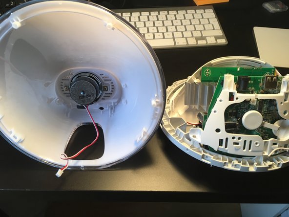
Here to note that you better remove the speaker connector and release the aerial wire removing the screw that fix it on the back. I had to replace the controller of the step-down 5 V supply, so i needed full access to the bottom board. Just to note that while reassembling I swapped by mistake the speaker and the buzzer connectors, they are the same... So be careful or you have to go through the tedious opening operation once again....
-


Annulation : je n'ai pas terminé ce tutoriel.
41 autres ont terminé cette réparation.
Merci à ces traducteurs :
100%

Suzanne Tessier nous aide à réparer le monde ! Vous voulez contribuer ?
Commencez à traduire ›

13 commentaires
Awesome teardown except for one little thing…
The factory sticker shows this is a 3530 which may not be different from a 3520. However, the bottom plate screw MUST be removed in order to separate the two halves. It is a little confusing saying “The bottom panel does not help gaining access to more screws. See next step.” I took that as being unnecessary, so skip.
I was able to fix my speaker inside it i got this alarm at a thrift store for cheap turns out the one wire just needed a better conenction to get working thank you for the steps to get to it
The first photo of step 5 is a little misleading, it looks like you are unscrewing something, it made me look for the screws
Other than that this was very helpful, thank you
3520 is very similar with the first steps identical. Many thanks for this guide!
I needed to get to the little switches because they are apparently the reason for a malfunction syndrome consisting of clicking noise and disabled menu sensors (according to a post which I have now lost the track of - my apologies). I gave the switches a gentle squirt of the well known panaceum known as WD40 which they sucked in greedily, following which I exercised them a little until the click sound became clear. Reassembling was a doddle. Now I am waiting for the WD40 to (mostly) evaporate while keeping my fingers crossed (this is a good procedure and a form of exercise). Then I shall switch the light on and we shall see how successful I was. Thanks again!
Yesterday my lamp was making a clicking sound and front LED was blinking with the sound. Now LED is not displayed and it looks like it's not powering up.
Any advice?
Ha! I see I wasn't the only one experiencing "has been working fine for years, and then the whole lamp stopped working, lamp and LED display.. No re[s]pons[e] what so ever". I was able to open it thanks to this guide (whoever designed the insides of the lamp at Philips must be some sort of BDSM lover!) but I couldn't find any fuse. I left it open for a couple of weeks while I've been out of the country and I tried to power it again (still disassembled) to see if I can just throw it out. And what do you know, it just worked! I took advantage that it was disassembled and I included a very small mod - an "audio out" connector - to be used for a future Home Assistant automation project. And then I put it back together, which was a success, considering that it looks the same as before, it works perfectly, it has the additional "audio out" connector AND I also was left with 2 screws! :)) I remember one of them was holding down the small antenna wire but the other one I still can't figure where it used to go
Thanks for showing how to disassemble. You helped me fix my unit :-).
Mine was acting up and maybe this can help others?:
It brightened the light when the alarm time was closed as it is supposed to, but when the alarm time was reached it turned off the light and locked up the buttons. Power had to be recycled to bring it back.
Turned out it was a bad 2200uF, 6.3v capacitor on the second PCB (the PCB connected with a flat ribbon cable to the PCB with the power connector. The PCB nearest the back cover is the one with the power connector)).
It is a capacitor located to the right on the PCB when you look at the component side. It is just next to the heat sink, so probably a bad location for a capacitor.
Desoldered the Capacitor measures "between" 27pF and "damaged component" in my component tester. A new capacitor seems to have solved the issue.
There is one screw under this tab that's hold the front ring attached in fact. I guess you should have removed it too before prying this ring open
Luuk Akkerman - Réponse
That one does not hold the ring but the cover (step 4).
Wozu das denn -